# Technical Document Extraction: Image Analysis
## Diagram Components and Flow
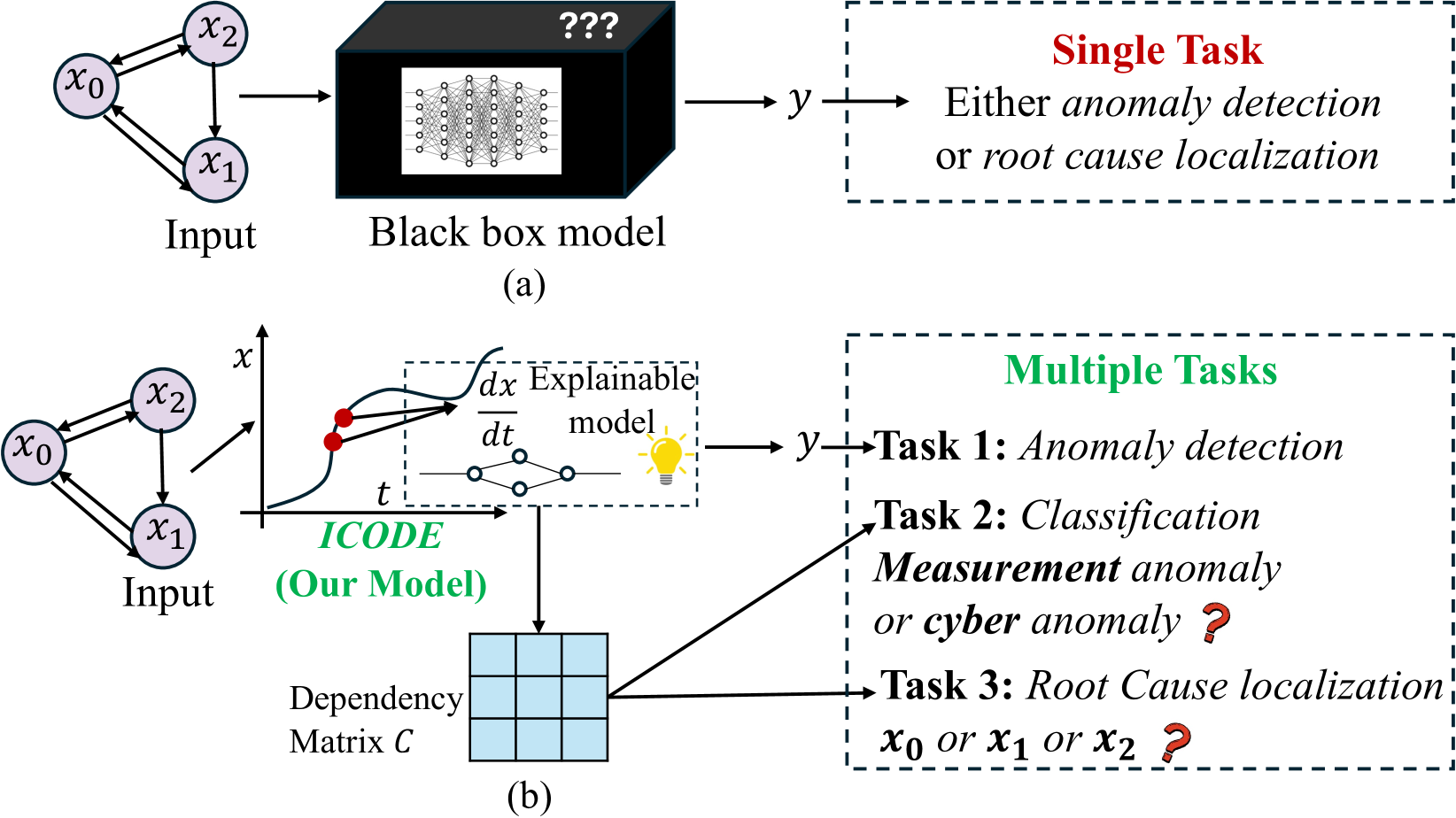
### Part (a): Black Box Model
- **Input Nodes**:
- `x₀` (labeled as "Input")
- `x₁`
- `x₂`
- **Black Box Model**:
- Represented as a black cube with internal structure (network diagram).
- Output labeled as `y`.
- **Tasks**:
- **Single Task** (highlighted in red):
- Options:
- `Anomaly detection`
- `Root cause localization`
### Part (b): IC Code Model
- **Input Nodes**:
- `x₀`, `x₁`, `x₂` (same as Part (a)).
- **Explainable Model**:
- Labeled as `dx/dt Explainable model` with a lightbulb icon.
- Visualized with a dashed box and derivative notation (`dx/dt`).
- **Dependency Matrix (C)**:
- 3x3 grid labeled "Dependency Matrix C".
- No numerical values provided (empty cells).
- **Tasks**:
- **Multiple Tasks** (highlighted in green):
1. **Task 1**: `Anomaly detection`
2. **Task 2**:
- `Classification`
- Sub-options:
- `Measurement anomaly`
- `Cyber anomaly` (marked with `?`)
3. **Task 3**:
- `Root Cause localization`
- Possible inputs: `x₀`, `x₁`, or `x₂` (marked with `?`)
## Key Observations
- **Color Coding**:
- Red (`Single Task`) vs. Green (`Multiple Tasks`).
- **Uncertainty Indicators**:
- Question marks (`?`) next to sub-options in Task 2 and Task 3.
- **Axes**:
- Part (b) includes axes labeled `x` (horizontal) and `t` (vertical).
- **Embedded Text**:
- "ICODE (Our Model)" in green, emphasizing the proposed framework.
## Structure Summary
1. **Input → Black Box Model → Output**:
- Single-task focus (anomaly detection or root cause localization).
2. **Input → IC Code Model → Dependency Matrix → Output**:
- Multi-task framework with explainable derivatives and dependency analysis.
3. **Task Ambiguities**:
- Cyber anomaly classification and root cause input localization are unresolved (marked with `?`).