## Diagram: Reward Machines (RM) for Agents $A_1, A_2,$ and $A_3$
### Overview
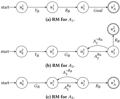
The image displays three distinct state machine diagrams, labeled (a), (b), and (c). These diagrams represent "Reward Machines" (RM) for three different agents, denoted as $A_1, A_2,$ and $A_3$. Each diagram illustrates a sequence of states and the specific conditions (transitions) required to progress from an initial state to a final goal state.
### Components/Axes
* **Nodes (Circles):** Represent the states of the agent (e.g., $u_0^1, u_1^1$).
* **Double Circles:** Represent the terminal or "Goal" state (e.g., $u_A^1$).
* **Arrows:** Represent directed transitions between states.
* **Labels on Arrows:** Represent the events or conditions required to trigger the transition.
* **"start" Label:** An arrow pointing to the initial state of each machine.
---
### Detailed Analysis
#### (a) RM for $A_1$
* **Structure:** A linear, non-branching sequence.
* **Flow:**
1. **Start** $\rightarrow u_0^1$
2. $u_0^1 \xrightarrow{Y_B} u_1^1$
3. $u_1^1 \xrightarrow{R_B} u_2^1$
4. $u_2^1 \xrightarrow{Goal} u_A^1$ (Goal state)
* **Trend:** This is a deterministic, linear progression. There are no loops or conditional resets.
#### (b) RM for $A_2$
* **Structure:** A sequence with a conditional loop at the end.
* **Flow:**
1. **Start** $\rightarrow u_0^2$
2. $u_0^2 \xrightarrow{Y_B} u_1^2$
3. $u_1^2 \xrightarrow{G_B} u_2^2$
4. $u_2^2 \xrightarrow{A_2^{R_B}} u_3^2$
5. **Loop:** From $u_3^2$, if the condition $A_2^{\neg R_B}$ occurs, the agent transitions back to $u_2^2$.
6. **Goal:** From $u_3^2$, if the condition $R_B$ occurs, the agent transitions to $u_A^2$ (Goal state).
* **Trend:** The agent progresses linearly until $u_2^2$, then enters a decision state ($u_3^2$) where it must satisfy $R_B$ to finish, or loop back to $u_2^2$ if $\neg R_B$ (not $R_B$) occurs.
#### (c) RM for $A_3$
* **Structure:** A sequence with a conditional loop in the middle.
* **Flow:**
1. **Start** $\rightarrow u_0^3$
2. $u_0^3 \xrightarrow{G_B} u_1^3$
3. $u_1^3 \xrightarrow{A_3^{R_B}} u_2^3$
4. **Loop:** From $u_2^3$, if the condition $A_3^{\neg R_B}$ occurs, the agent transitions back to $u_1^3$.
5. **Goal:** From $u_2^3$, if the condition $R_B$ occurs, the agent transitions to $u_A^3$ (Goal state).
* **Trend:** Similar to $A_2$, this agent has a conditional loop, but the loop occurs earlier in the sequence (at $u_2^3$ returning to $u_1^3$) compared to $A_2$.
---
### Key Observations
* **Notation:** The superscript number on the states ($u^1, u^2, u^3$) corresponds to the agent index ($A_1, A_2, A_3$).
* **Conditional Logic:** The symbols $\neg R_B$ represent the logical negation of $R_B$ (i.e., "not $R_B$").
* **Complexity:** $A_1$ is the simplest (linear), while $A_2$ and $A_3$ introduce non-deterministic or reactive behavior via loops, requiring specific conditions to be met to exit the loop and reach the goal.
### Interpretation
These diagrams are formal specifications for task completion in a Reinforcement Learning or automated planning context.
* **Task Structure:**
* $A_1$ represents a "fixed-sequence" task where events $Y_B$ and $R_B$ must happen in order.
* $A_2$ and $A_3$ represent "retry" tasks. They require the agent to reach a specific state and then successfully trigger event $R_B$. If the agent fails to trigger $R_B$ (indicated by $\neg R_B$), it is forced to return to a previous state to try again.
* **Design Intent:** The difference in loop placement between $A_2$ and $A_3$ suggests that $A_3$ has a "shorter" path to the goal if the condition $R_B$ is met, but potentially a different penalty structure (returning to $u_1^3$ vs $u_2^2$) if the condition is not met. This implies these agents are operating in environments where the availability of the "Goal" or "Success" event ($R_B$) is stochastic or dependent on the agent's current state.