## Diagram: LLM-Driven Bug Fixing and Test Writing Workflow
### Overview
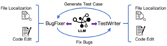
This image is a technical workflow diagram illustrating an automated, cyclical software development process powered by a Large Language Model (LLM). It depicts a dual-agent system consisting of a "BugFixer" and a "TestWriter," both of which utilize the central LLM to perform specific tasks (File Localization and Code Edit) in a continuous feedback loop.
### Components
The diagram contains no axes or charts; it is composed entirely of text labels, icons, and directional arrows.
**Central Elements:**
* **Icon:** A stylized neural network/graph node symbol (black and white circles connected by curved lines).
* **Text:** **LLM** (bold, black text centered directly below the network icon).
* **Directional Indicators:** Two short, thick purple arrows pointing outward from the central LLM icon—one pointing left towards the "BugFixer," and one pointing right towards the "TestWriter."
**Left Region (BugFixer):**
* **Text:** **BugFixer** (positioned to the left of the central LLM).
* **Grouping Element:** A large blue curly bracket `}` groups the far-left elements and points inward toward the "BugFixer" text.
* **Top-Left Sub-component:**
* Text: **File Localization**
* Icon: A document with a magnifying glass over it.
* **Bottom-Left Sub-component:**
* Text: **Code Edit**
* Icon: A document with a pen writing on it.
**Right Region (TestWriter):**
* **Text:** **TestWriter** (positioned to the right of the central LLM).
* **Grouping Element:** A large blue curly bracket `{` groups the far-right elements and points inward toward the "TestWriter" text.
* **Top-Right Sub-component:**
* Text: **File Localization**
* Icon: A document with a magnifying glass over it.
* **Bottom-Right Sub-component:**
* Text: **Code Edit**
* Icon: A document with a pen writing on it.
**Cyclical Flow Elements (Top and Bottom):**
* **Top Flow:** A long, curved blue arrow originating from "TestWriter" and pointing leftward to "BugFixer".
* Label: **Generate Test Case** (centered above the arrow).
* **Bottom Flow:** A long, curved blue arrow originating from "BugFixer" and pointing rightward to "TestWriter".
* Label: **Fix Bugs** (centered below the arrow).
### Content Details (Workflow Flow)
1. **Core Engine:** The central **LLM** acts as the foundational intelligence. The purple arrows indicate that the LLM powers or instantiates both the **BugFixer** and the **TestWriter** agents.
2. **Agent Capabilities:** Both the BugFixer and the TestWriter possess identical foundational capabilities, as indicated by the symmetrical brackets on the far left and far right. Both agents can perform **File Localization** (finding the relevant code) and **Code Edit** (modifying the code).
3. **The Loop:**
* The **TestWriter** utilizes its capabilities to **Generate Test Case**s, which are then passed to the **BugFixer** (indicated by the top blue arrow).
* The **BugFixer** receives the test cases, utilizes its capabilities to **Fix Bugs** in the code to satisfy the tests, and passes the results back to the **TestWriter** (indicated by the bottom blue arrow).
### Key Observations
* **Symmetry:** The diagram is highly symmetrical. The capabilities on the far left and far right are identical in both text and iconography, highlighting that while the *roles* (BugFixer vs. TestWriter) are different, the underlying *actions* they perform on the codebase (finding files, editing text) are the same.
* **Closed Loop:** The blue arrows create a closed, continuous feedback loop. This implies an iterative process that continues until a certain condition (likely passing tests) is met.
* **Single Brain, Dual Persona:** The purple arrows diverging from a single LLM suggest that one underlying model is being prompted or fine-tuned to act as two distinct adversarial or cooperative personas.
### Interpretation
This diagram represents an architecture for an autonomous, AI-driven software debugging system based on the principles of Test-Driven Development (TDD).
By separating the tasks into two distinct LLM-driven agents, the system creates a "maker-checker" dynamic. The **TestWriter** acts as the specifier and verifier, writing tests that define the expected behavior or expose a bug. The **BugFixer** acts as the developer, attempting to alter the code to make the tests pass.
Because both agents have "File Localization" and "Code Edit" capabilities, it implies they are operating directly on a repository. The TestWriter finds where to put the tests and writes them; the BugFixer finds the faulty source code and alters it. The cyclical arrows demonstrate an automated iterative loop: the TestWriter writes a failing test, the BugFixer edits the code to fix it, the TestWriter evaluates the fix (and potentially writes more tests if it fails or breaks something else), and the cycle repeats. This architecture is designed to reduce human intervention in the debugging process by using AI to both identify/prove the bug and generate the solution.