\n
## Diagram: Kernel Execution Flow with Local Synchronization
### Overview
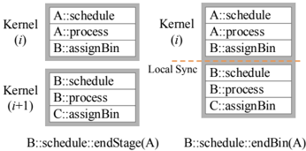
The image depicts a diagram illustrating the execution flow of two kernels, labeled (i) and (i+1), with a local synchronization point between them. The diagram shows a sequence of operations (schedule, process, assignBin) performed by different entities (A, B, C) within each kernel. A dashed orange line indicates the synchronization point and associated operation.
### Components/Axes
The diagram consists of two rectangular blocks representing Kernel (i) and Kernel (i+1). Each kernel block contains three rows, representing operations. Each row is labeled with an entity followed by a double colon and the operation name. The diagram also includes a label "Local Sync" pointing to the dashed orange line. Text labels at the bottom of the diagram specify the operation performed during synchronization.
### Detailed Analysis or Content Details
**Kernel (i):**
* A::schedule
* A::process
* B::assignBin
**Kernel (i+1):**
* B::schedule
* B::process
* C::assignBin
**Synchronization:**
* The dashed orange line connects the bottom of Kernel (i) to the middle of Kernel (i+1).
* The label "Local Sync" is positioned near the dashed line.
* The text label below Kernel (i) reads: "B::schedule::endStage(A)"
* The text label below Kernel (i+1) reads: "B::schedule::endBin(A)"
### Key Observations
The diagram illustrates a sequential dependency between the two kernels. Kernel (i+1) cannot proceed until Kernel (i) has completed a specific operation involving entity B. The synchronization point involves entity B scheduling the end of stage A and the end of bin A.
### Interpretation
This diagram likely represents a computational pipeline or a multi-stage processing system. The kernels represent distinct processing stages, and the synchronization point ensures that data dependencies are met before proceeding to the next stage. The operations "schedule," "process," and "assignBin" suggest a resource allocation or data partitioning scheme. The synchronization mechanism ensures that entity B correctly manages the completion of stage A before initiating the next stage. The use of "endStage" and "endBin" suggests a specific data structure or organizational unit within the system. The diagram highlights the importance of synchronization in maintaining data consistency and correct execution order in parallel or distributed computing environments. The diagram suggests a workflow where A performs some initial processing, B assigns data to bins, and then B schedules the completion of these operations. The synchronization ensures that A's stage is fully completed before B moves on to the next bin.