## Diagram: Kernel Scheduling and Synchronization Flow
### Overview
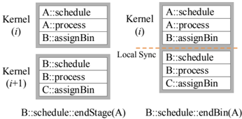
The diagram illustrates the interaction between two consecutive kernels (Kernel i and Kernel i+1) in a parallel computing or distributed system. It highlights the flow of data, synchronization points, and the assignment of bins (likely memory or resource allocation) between kernels. The diagram uses labeled boxes, arrows, and function calls to represent the process.
---
### Components/Axes
1. **Kernels**:
- **Kernel (i)**: Contains three entries:
- `A::schedule`
- `A::process`
- `B::assignBin`
- **Kernel (i+1)**: Contains three entries:
- `B::schedule`
- `B::process`
- `C::assignBin`
2. **Local Sync**:
- A dashed horizontal line connects `B::schedule` (Kernel i) and `B::process` (Kernel i+1), indicating a synchronization point.
3. **Arrows**:
- Two arrows labeled with function calls:
- `B::schedule::endStage(A)` (from Kernel i to Kernel i+1)
- `B::schedule::endBin(A)` (from Kernel i to Kernel i+1)
---
### Detailed Analysis
- **Kernel i**:
- `A::schedule`: Likely represents the scheduling phase for kernel A.
- `A::process`: Represents the processing phase for kernel A.
- `B::assignBin`: Assigns a bin (resource or memory) for kernel B.
- **Kernel i+1**:
- `B::schedule`: Scheduling phase for kernel B.
- `B::process`: Processing phase for kernel B.
- `C::assignBin`: Assigns a bin for kernel C.
- **Local Sync**:
- The dashed line between `B::schedule` (Kernel i) and `B::process` (Kernel i+1) suggests a barrier or synchronization mechanism to ensure data consistency or resource availability before proceeding.
- **Arrows**:
- `B::schedule::endStage(A)`: Indicates the completion of a stage (e.g., a phase of computation) for kernel A, triggering the next kernel's execution.
- `B::schedule::endBin(A)`: Signals the completion of bin assignment for kernel A, allowing kernel B to proceed.
---
### Key Observations
1. **Synchronization Dependency**:
- The local sync between `B::schedule` and `B::process` ensures that kernel B's processing only begins after its scheduling is finalized.
2. **Resource Assignment Flow**:
- `B::assignBin` in Kernel i assigns a bin for kernel B, which is then used in `B::schedule` and `B::process` in Kernel i+1.
3. **Function Calls**:
- The arrows with `endStage` and `endBin` suggest that kernel i's completion of specific tasks (stage and bin assignment) directly enables kernel i+1's execution.
---
### Interpretation
This diagram represents a **pipeline or staged execution model** where kernels are executed sequentially but with explicit synchronization points. The use of `assignBin` implies resource management (e.g., memory or compute units) is critical to the workflow. The `endStage` and `endBin` functions act as triggers for the next kernel, ensuring that each stage is completed before proceeding. The synchronization between `B::schedule` and `B::process` highlights the importance of coordination between scheduling and execution phases to avoid race conditions or resource conflicts. The progression from `A` to `B` to `C` in `assignBin` suggests a hierarchical or cascading resource allocation strategy.
---
### Notes
- No numerical data or charts are present; the diagram focuses on structural and functional relationships.
- The absence of a legend or color-coded data series simplifies interpretation but limits quantitative analysis.
- The diagram assumes a left-to-right flow of execution, typical in sequential or pipelined systems.