## Diagram: Hierarchical Tree Structure
### Overview
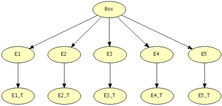
The image displays a simple hierarchical tree diagram with a single root node and two levels of child nodes. The diagram illustrates a one-to-many relationship originating from a central entity, with each branch terminating in a distinct endpoint. The structure is symmetrical and uses consistent labeling conventions.
### Components/Axes
* **Root Node:** A single oval at the top center labeled **"Box"**.
* **First-Level Nodes:** Five ovals arranged horizontally in a row below the root, labeled **"E1"**, **"E2"**, **"E3"**, **"E4"**, and **"E5"** from left to right.
* **Second-Level (Terminal) Nodes:** Five ovals arranged horizontally in a row at the bottom, directly below their parent nodes. They are labeled **"E1_T"**, **"E2_T"**, **"E3_T"**, **"E4_T"**, and **"E5_T"** from left to right.
* **Connections (Edges):** Directed arrows (lines with arrowheads) indicate the flow or relationship:
* Five arrows originate from the bottom of the "Box" node, each pointing to one of the first-level nodes (E1 through E5).
* Five arrows originate from the bottom of each first-level node (E1 through E5), each pointing directly down to its corresponding second-level node (E1_T through E5_T).
### Detailed Analysis
* **Spatial Layout:** The diagram is organized in three distinct horizontal tiers.
* **Top Tier (Center):** Contains the root node "Box".
* **Middle Tier:** Contains the five primary child nodes (E1-E5), evenly spaced.
* **Bottom Tier:** Contains the five terminal nodes (E1_T-E5_T), each vertically aligned directly beneath its parent in the middle tier.
* **Node Relationships:** The structure defines a strict parent-child hierarchy. "Box" is the parent of E1, E2, E3, E4, and E5. Each of these (E1-E5) is, in turn, the sole parent of its corresponding terminal node (E1_T-E5_T). There are no cross-connections between branches.
* **Labeling Pattern:** The labels follow a clear pattern. The first-level nodes use a base identifier ("E" followed by a number 1-5). The second-level nodes append the suffix "_T" to the identifier of their direct parent (e.g., E1's child is E1_T). The root node uses a distinct, non-sequential label ("Box").
### Key Observations
1. **Symmetry and Uniformity:** The diagram is perfectly symmetrical. Each of the five branches has an identical structure: one parent node leading to one child node.
2. **Consistent Naming Convention:** The "_T" suffix is applied uniformly to all terminal nodes, suggesting a common property or state (e.g., "Terminal," "Transformed," "Type," or "Target").
3. **Directional Flow:** All arrows point downward, indicating a top-down flow of control, dependency, or derivation from the general ("Box") to the specific (E1...E5) and finally to a terminal state (E1_T...E5_T).
4. **Lack of Additional Data:** The diagram contains no numerical data, quantitative scales, color coding (beyond the uniform pale yellow fill of the nodes), or descriptive annotations beyond the node labels.
### Interpretation
This diagram represents a foundational hierarchical or taxonomic structure. The "Box" likely symbolizes a container, a system, a process, or a category that encompasses or generates five distinct entities or components (E1-E5). Each of these entities then leads to a specific, final outcome, version, or type (E1_T-E5_T).
The structure suggests a one-to-five decomposition followed by a one-to-one transformation or specification. It could model:
* A **data schema** where a main table ("Box") relates to five child tables, each with a corresponding temporary or test version ("_T").
* A **process flow** where a central task spawns five sub-tasks, each concluding with a terminal step.
* A **classification system** where a broad category is divided into five classes, each with a defined terminal type.
The absence of specific details (what "Box," "E," or "_T" actually represent) means the diagram is a generic template. Its primary informational value is in illustrating the *pattern* of relationships: a single source branching into multiple parallel paths, each with a consistent, linear progression to an endpoint. The perfect symmetry implies equal weight or importance is given to all five branches within the system being modeled.