\n
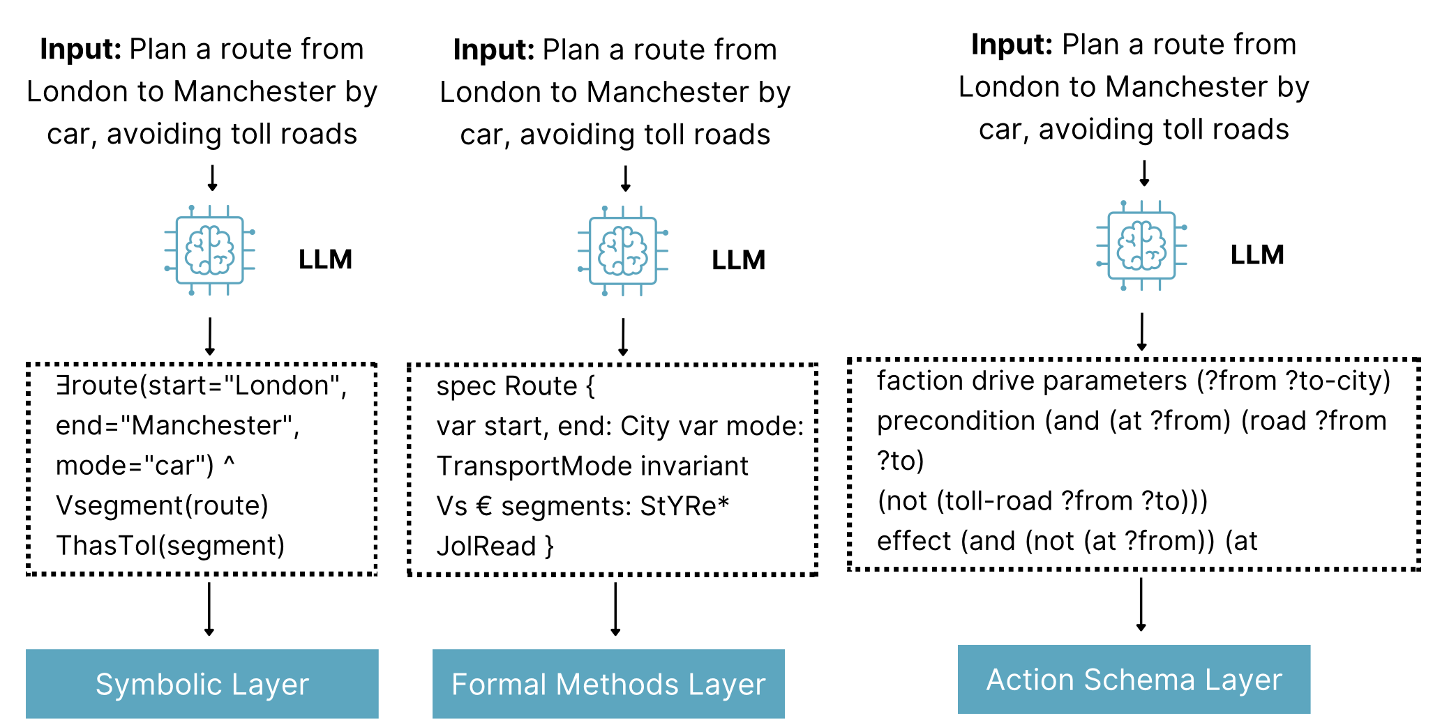
## Diagram: LLM Route Planning Pipeline
### Overview
The image depicts a three-column diagram illustrating a pipeline for route planning using a Large Language Model (LLM). Each column represents a different layer – Symbolic, Formal Methods, and Action Schema – and shows how the same input ("Plan a route from London to Manchester by car, avoiding toll roads") is processed through each layer, resulting in different outputs.
### Components/Axes
The diagram consists of three main columns, each representing a layer. Each column has the following components:
1. **Input:** A text description of the route planning request.
2. **LLM:** A stylized representation of a Large Language Model.
3. **Intermediate Representation:** A block of text representing the output of the LLM in that specific layer. The text is enclosed in a dashed box.
4. **Layer Label:** A colored rectangle at the bottom indicating the layer name (Symbolic, Formal Methods, Action Schema).
### Content Details
**Column 1: Symbolic Layer**
* **Input:** "Input: Plan a route from London to Manchester by car, avoiding toll roads"
* **LLM:** A blue stylized LLM icon.
* **Intermediate Representation:** "∃route(start="London", end="Manchester", mode="car") ∧ ∀segment(route) ThasTol(segment)"
* **Layer Label:** "Symbolic Layer" (Teal rectangle)
**Column 2: Formal Methods Layer**
* **Input:** "Input: Plan a route from London to Manchester by car, avoiding toll roads"
* **LLM:** A blue stylized LLM icon.
* **Intermediate Representation:** "spec Route { var start, end: City var mode: TransportMode invariant Vs ∈ segments: StYRe* JoIRead }"
* **Layer Label:** "Formal Methods Layer" (Green rectangle)
**Column 3: Action Schema Layer**
* **Input:** "Input: Plan a route from London to Manchester by car, avoiding toll roads"
* **LLM:** A blue stylized LLM icon.
* **Intermediate Representation:** "faction drive parameters (?from ?to-city) precondition (and (at ?from) (road ?from ?to) (not (toll-road ?from ?to))) effect (and (not ?from) (at ?to))"
* **Layer Label:** "Action Schema Layer" (Light Blue rectangle)
### Key Observations
The diagram demonstrates how the same high-level request is transformed into different formal representations depending on the layer. The Symbolic Layer uses existential and universal quantifiers. The Formal Methods Layer uses a specification format with variables and invariants. The Action Schema Layer uses a precondition/effect style representation.
### Interpretation
This diagram illustrates a multi-layered approach to grounding LLM outputs in formal systems. The LLM acts as a translator, converting natural language into representations suitable for different reasoning and execution frameworks. Each layer provides a different level of abstraction and formality.
* **Symbolic Layer:** Represents a basic logical formulation of the request.
* **Formal Methods Layer:** Provides a more structured and verifiable specification.
* **Action Schema Layer:** Defines the actions and conditions required to execute the route planning task.
The diagram suggests a system where the LLM is not directly executing the route planning, but rather generating formal representations that can be used by other systems (e.g., a route planner, a verification tool). The use of different layers allows for flexibility and integration with various tools and techniques. The diagram highlights the importance of bridging the gap between natural language understanding and formal reasoning. The consistent input across all layers emphasizes the LLM's role as a consistent interface.