\n
## Diagram: LLM-Mediated Translation of Natural Language to Formal Representations
### Overview
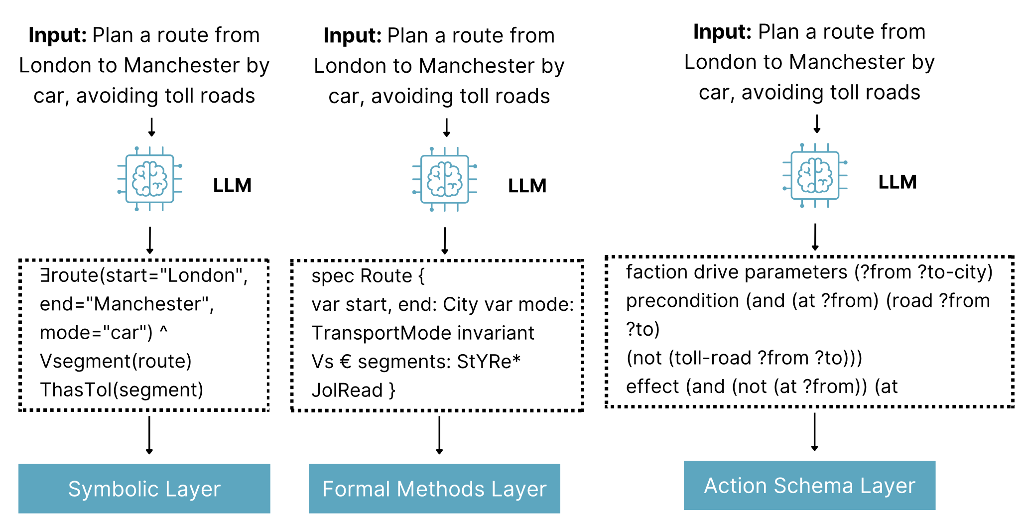
The image is a technical diagram illustrating three parallel pipelines where the same natural language input is processed by a Large Language Model (LLM) to generate three distinct formal representations. Each representation is designed for integration with a different computational layer: a Symbolic Layer, a Formal Methods Layer, and an Action Schema Layer. The diagram demonstrates the LLM's role as a translator between human language and machine-executable or verifiable formalisms.
### Components/Axes
The diagram is organized into three vertical columns, each representing a complete pipeline. The components in each column, from top to bottom, are:
1. **Input Block (Top):** Identical text in all three columns.
* **Text:** `Input: Plan a route from London to Manchester by car, avoiding toll roads`
2. **Processing Unit (Middle):** An icon of a brain inside a microchip, labeled with the text `LLM`. A downward arrow connects the Input Block to this icon.
3. **Formal Output Block (Center):** A dashed rectangular box containing code or formal logic text. A downward arrow connects the LLM icon to this box. The content of this box differs for each column.
4. **Target Layer Block (Bottom):** A solid, teal-colored rectangular box with white text. A downward arrow connects the Formal Output Block to this box. The label differs for each column.
### Detailed Analysis
**Column 1 (Left):**
* **Formal Output Block Content:**
```
∃route(start="London",
end="Manchester",
mode="car") ^
Vsegment(route)
ThasTol(segment)
```
* **Transcription Notes:** Uses logical symbols (∃ for "there exists", ^ for "and"). "Vsegment" and "ThasTol" appear to be predicate or function names. The text is precisely as shown, including potential typos or shorthand (e.g., "ThasTol").
* **Target Layer Label:** `Symbolic Layer`
**Column 2 (Center):**
* **Formal Output Block Content:**
```
spec Route {
var start, end: City var mode:
TransportMode invariant
Vs € segments: StYRe*
JolRead }
```
* **Transcription Notes:** Resembles a specification language. Contains potential typos or non-standard notation: "Vs € segments" (likely meaning "for all segments in..."), "StYRe*", and "JolRead". The text is transcribed exactly as visible.
* **Target Layer Label:** `Formal Methods Layer`
**Column 3 (Right):**
* **Formal Output Block Content:**
```
faction drive parameters (?from ?to-city)
precondition (and (at ?from) (road ?from
?to)
(not (toll-road ?from ?to)))
effect (and (not (at ?from)) (at
```
* **Transcription Notes:** Uses a Lisp-like syntax with parentheses. The first word is likely a typo for "action". The text is cut off at the end, ending with `(at`. The transcription includes this incomplete line.
* **Target Layer Label:** `Action Schema Layer`
### Key Observations
1. **Identical Input, Divergent Outputs:** The core observation is that a single, unambiguous natural language command is transformed into three syntactically and semantically distinct formal outputs.
2. **Specialization of Output:** Each output format is tailored to a specific domain:
* The **Symbolic Layer** output uses existential quantification and logical predicates, suitable for symbolic AI reasoning.
* The **Formal Methods Layer** output uses a typed specification with invariants, suitable for software or system verification.
* The **Action Schema Layer** output uses a planning domain definition language (PDDL)-like structure with parameters, preconditions, and effects, suitable for automated planning systems.
3. **Potential Artifacts:** The text in the Formal Output Blocks contains what appear to be typos, shorthand, or non-standard notation (`ThasTol`, `StYRe*`, `JolRead`, `faction`). This may indicate the diagram is illustrating a conceptual or research-stage process rather than a polished product.
4. **Visual Flow:** The flow is strictly top-down and linear within each column, with no interaction shown between the columns. The identical LLM icon suggests the same model (or model type) is capable of all three translations.
### Interpretation
This diagram illustrates a key concept in modern AI systems: using LLMs as a "universal translator" or interface layer between human communication and specialized computational back-ends.
* **What it demonstrates:** The LLM is not just generating a text response; it is performing a **structured translation task**. It parses the intent ("plan a route," "avoid tolls") and the constraints ("London," "Manchester," "car") from the input and maps them onto the precise syntax and semantics required by three different formal systems.
* **Why it matters:** This capability is crucial for building practical AI agents. It allows a user to interact with complex, rigid systems (like planners, verifiers, or logic engines) using flexible natural language. The LLM bridges the "communication gap."
* **Underlying Pattern:** The diagram highlights the **modularity** of such an architecture. The LLM acts as a front-end processor. The downstream "Symbolic," "Formal Methods," and "Action Schema" layers can be developed, optimized, and validated independently, as long as they adhere to the input format the LLM is trained to produce.
* **Notable Anomaly:** The presence of apparent errors or non-standard notations in the formal outputs is significant. It suggests the translation process may not be perfect or that the diagram is capturing a specific, perhaps experimental, formalism. In a real-world application, these outputs would need to be syntactically valid for their respective layers to function.