## Diagram: Neural Network Architecture Block Diagram
### Overview
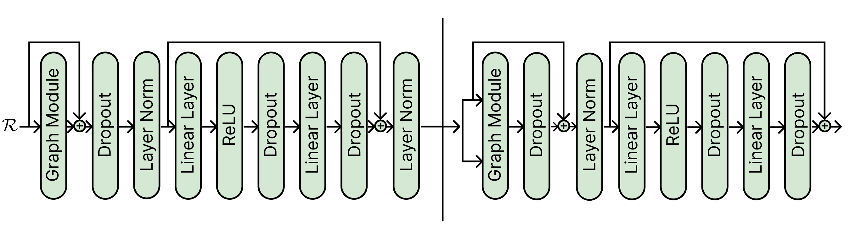
The image displays a detailed block diagram of a neural network architecture, specifically illustrating the data flow and layer composition of two sequential processing blocks or stages. The diagram uses rounded rectangular nodes to represent different layer types, connected by directional arrows indicating the forward pass. A vertical line separates the diagram into two distinct, but structurally similar, major sections. The overall flow is from left to right.
### Components/Axes
**Input:**
* **ℛ**: Located at the far left, this symbol (likely representing a representation, feature map, or tensor) is the input to the entire architecture.
**Layer Types (Nodes):**
The following layer types are used as building blocks, listed in the order they first appear:
1. **Graph Module**
2. **Dropout**
3. **Layer Norm**
4. **Linear Layer**
5. **ReLU**
6. **Linear Layer** (second instance)
7. **Dropout** (second instance)
8. **Layer Norm** (second instance)
**Connectivity Elements:**
* **Arrows**: Indicate the primary sequential data flow between layers.
* **Skip Connections / Residual Paths**: Represented by arrows that bypass one or more layers. These paths originate before a block of layers and terminate at a summation point (⊕) after the block, where the bypassed signal is added to the processed signal.
* **⊕ (Summation Point)**: A circle with a plus sign, indicating element-wise addition of the main path and a skip connection.
* **Vertical Line**: A solid black line dividing the diagram into a left section (first block) and a right section (second block).
### Detailed Analysis
**Left Section (First Block):**
1. The input **ℛ** splits into two paths:
* **Main Path**: Flows into a **Graph Module**.
* **Skip Connection**: Bypasses the Graph Module.
2. The outputs of the Graph Module and the skip connection meet at a **summation point (⊕)**.
3. The summed signal then flows sequentially through: **Dropout** → **Layer Norm** → **Linear Layer** → **ReLU** → **Dropout** → **Linear Layer** → **Dropout**.
4. After the final Dropout in this sequence, another **skip connection** originates from the point *after the first Layer Norm* (i.e., before the first Linear Layer) and connects to a second **summation point (⊕)**.
5. The output of this second summation flows into a final **Layer Norm**.
6. The output of this Layer Norm is the output of the left section and becomes the input to the right section.
**Right Section (Second Block):**
1. The input from the left section splits into two paths:
* **Main Path**: Flows into a **Graph Module**.
* **Skip Connection**: Bypasses the Graph Module.
2. The outputs meet at a **summation point (⊕)**.
3. The summed signal flows sequentially through: **Dropout** → **Layer Norm** → **Linear Layer** → **ReLU** → **Dropout** → **Linear Layer** → **Dropout**.
4. After the final Dropout, a **skip connection** originates from the point *after the Layer Norm* (i.e., before the first Linear Layer in this block) and connects to a final **summation point (⊕)**.
5. The output of this final summation is the output of the entire depicted architecture.
### Key Observations
1. **Residual Learning Framework**: The architecture heavily utilizes residual (skip) connections, a hallmark of modern deep networks (e.g., ResNets) designed to mitigate the vanishing gradient problem and enable training of deeper models.
2. **Two-Stage Processing**: The vertical line suggests the model is composed of at least two major, potentially repeated, blocks or stages. The second block is not an exact copy of the first; its first skip connection bypasses only the Graph Module and Dropout, whereas the first block's initial skip bypasses only the Graph Module.
3. **Layer Composition**: Each block combines:
* **Graph-based processing** (Graph Module).
* **Regularization** (Dropout layers appear frequently).
* **Normalization** (Layer Norm).
* **Linear transformations** (Linear Layers).
* **Non-linear activation** (ReLU).
4. **Pattern of Operations**: A common sub-pattern within each block is: `Linear Layer -> ReLU -> Dropout -> Linear Layer -> Dropout`, which is a standard feed-forward network structure often found in Transformer architectures.
### Interpretation
This diagram represents a sophisticated deep learning model designed for tasks where relational or graph-structured data is important, as indicated by the "Graph Module." The architecture is engineered for stability and depth through the extensive use of Layer Normalization and residual connections.
The flow suggests a hybrid model: it first processes input through a graph-aware operation, then passes the result through a series of transformations that resemble a Transformer's feed-forward sublayer (Linear-ReLU-Dropout-Linear-Dropout). The residual connections are strategically placed to allow gradients to flow directly through the network during backpropagation, facilitating the training of a deep stack of such blocks.
The separation into two blocks by the vertical line could indicate a hierarchical feature extraction process, where the first block processes low-level graph features and the second block processes higher-level abstractions. The slight variation in skip connection topology between the two blocks might be an architectural choice to create different levels of feature refinement or to control the information flow. Overall, this is a blueprint for a deep graph neural network with strong regularization and normalization components.