## Diagram: Expression Evaluation Graph
### Overview
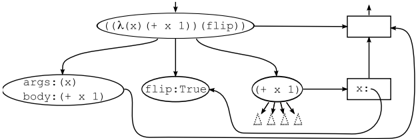
The image depicts a directed graph representing the evaluation of an expression involving a lambda function, function application, and a conditional flip. The graph shows the flow of data and operations, with nodes representing expressions or values and edges indicating dependencies or function calls.
### Components/Axes
* **Nodes:** The nodes are represented by ovals and rectangles. Ovals contain expressions or values, while rectangles represent operations or assignments.
* **Edges:** The edges are represented by arrows, indicating the direction of data flow or function calls.
* **Root Node:** A node at the top center, with an incoming arrow, represents the initial expression to be evaluated.
* **Expression Node:** An oval node containing the expression `((λ(x) (+ x 1)) (flip))`.
* **Argument Node:** An oval node labeled `args: (x)` and `body: (+ x 1)`.
* **Flip Node:** An oval node labeled `flip: True`.
* **Addition Node:** An oval node labeled `(+ x 1)`.
* **Undefined Values:** Four small triangle symbols pointing downwards, connected to the addition node.
* **Operation Nodes:** Two rectangular nodes on the right side of the diagram. The bottom rectangle is labeled `x:`.
* **Loop:** A loop is formed by edges connecting the rectangular nodes.
### Detailed Analysis
1. **Top Node:** The evaluation starts from the top node, which is not labeled.
2. **Expression Evaluation:** The expression `((λ(x) (+ x 1)) (flip))` is evaluated. This involves applying the lambda function `λ(x) (+ x 1)` to the argument `(flip)`.
3. **Argument and Body:** The `args: (x)` and `body: (+ x 1)` node represents the lambda function's structure.
4. **Flip Condition:** The `flip: True` node represents a boolean value.
5. **Addition Operation:** The `(+ x 1)` node represents the addition operation. It receives input from the `x:` node.
6. **Undefined Values:** The four triangles below the `(+ x 1)` node likely represent undefined or uninitialized values being passed into the addition operation.
7. **Assignment:** The `x:` node represents the assignment of a value to the variable `x`.
8. **Loop:** The loop formed by the rectangular nodes suggests an iterative process or recursion.
### Key Observations
* The diagram illustrates the evaluation of a complex expression involving function application and conditional logic.
* The use of `flip: True` suggests a conditional branch in the evaluation.
* The presence of undefined values in the addition operation indicates a potential error or incomplete evaluation.
* The loop structure suggests a recursive or iterative process.
### Interpretation
The diagram visualizes the execution flow of a functional program. The initial expression `((λ(x) (+ x 1)) (flip))` is the entry point. The `flip: True` node likely controls whether the lambda function is applied or not. The `(+ x 1)` node represents a calculation, but the undefined values suggest that the input `x` might not always be properly initialized. The loop on the right side indicates a repeated process, possibly related to the conditional application of the lambda function. The diagram highlights the dependencies between different parts of the expression and the flow of data during evaluation. The undefined values and the loop suggest potential areas for further investigation or optimization.