## Flowchart: Function Application with Conditional Branching
### Overview
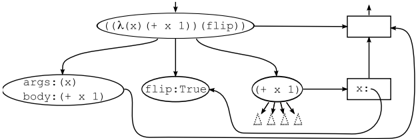
The diagram illustrates a computational process involving function application, conditional branching, and variable assignment. It depicts a recursive-like structure with feedback loops and decision points, likely representing an algorithm for transforming input values through mathematical operations and state-dependent logic.
### Components/Axes
1. **Primary Function Node**
- Oval labeled: `(λ(x) (+ x 1)) (flip)`
- Represents a lambda function that increments input `x` by 1, with a `(flip)` modifier.
2. **Decision/Output Node**
- Rectangle connected to the primary function node.
- Contains an arrow looping back to the primary function, suggesting iterative processing.
3. **Branching Paths**
- **Path 1**: Leads to an oval labeled:
- `args: (x)`
- `body: (+ x 1)`
- Defines function parameters and operation.
- **Path 2**: Connects to a circle labeled:
- `flip:True`
- Indicates a conditional flag or state variable.
- **Path 3**: Links to a rectangle labeled:
- `(+ x 1)`
- Contains a variable assignment node labeled `x:`.
4. **Feedback Loop**
- Arrows connect the output rectangle back to the primary function node, creating a cyclical process.
5. **Parallel Processing Indicators**
- Three downward-pointing triangles beneath the `(+ x 1)` rectangle, possibly representing concurrent operations or multiple execution paths.
### Detailed Analysis
- **Function Definition**: The primary node defines a lambda function `λ(x)` that computes `x + 1`, modified by `(flip)`, which may invert behavior or trigger a state change.
- **Conditional Logic**: The `flip:True` node acts as a gatekeeper, potentially enabling/disabling subsequent operations based on its boolean value.
- **Variable Propagation**: The `(+ x 1)` operation is both part of the function definition and the output assignment, suggesting the result of the computation is fed back into the system.
- **Recursive Structure**: The feedback loop implies the function may execute repeatedly, with `x` being updated iteratively (e.g., `x := x + 1` in each cycle).
### Key Observations
1. **Cyclical Dependency**: The output of the `(+ x 1)` operation directly influences the input of the primary function, creating a self-reinforcing loop.
2. **Conditional Branching**: The `flip:True` node introduces a binary decision point, though its exact role (e.g., toggling function behavior) is not explicitly defined.
3. **Ambiguous Terminology**: The `(flip)` modifier lacks context—it could represent a mathematical operation, a state variable, or a control flag.
4. **Parallelism**: The triangles beneath the `(+ x 1)` node suggest concurrent processing, but their relationship to the main flow is unclear.
### Interpretation
This flowchart likely models a recursive algorithm where:
- A function increments an input value `x` by 1.
- A conditional (`flip:True`) determines whether the result is propagated back into the system.
- The feedback loop enables iterative computation, potentially for tasks like sequence generation or state machine simulation.
The ambiguity around `(flip)` and the purpose of parallel processing hints at incomplete documentation. The diagram emphasizes functional composition and state management but lacks explicit termination conditions or error-handling logic. The use of `(λ(x) (+ x 1))` suggests a Lisp-like syntax, indicating the diagram may represent a functional programming paradigm.