## Diagram: Neural Synapse with Memristive Synaptic Plasticity
### Overview
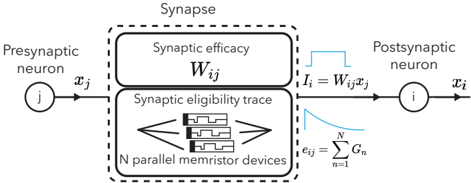
The diagram illustrates a computational model of synaptic transmission and plasticity in a neural network. It depicts the interaction between a presynaptic neuron, synaptic efficacy, memristive devices representing synaptic eligibility traces, and a postsynaptic neuron. The flow of information and synaptic modification mechanisms are explicitly labeled.
---
### Components/Axes
1. **Presynaptic Neuron**
- Labeled with `x_j` (input signal).
- Positioned on the left side of the diagram.
2. **Synaptic Efficacy**
- Labeled as `W_ij` (synaptic weight).
- Located in the upper section of the dashed "Synapse" box.
3. **Synaptic Eligibility Trace**
- Represented by `N parallel memristor devices`.
- Positioned below the synaptic efficacy label.
- Conductance values denoted as `G_n` (n = 1 to N).
4. **Postsynaptic Neuron**
- Labeled with `x_i` (output signal).
- Positioned on the right side of the diagram.
5. **Current Flow**
- `I_i = W_ij * x_j` (input current to postsynaptic neuron).
- `e_ij = Σ G_n` (sum of memristor conductances).
---
### Detailed Analysis
- **Presynaptic to Postsynaptic Pathway**:
The presynaptic neuron (`x_j`) transmits a signal to the synaptic efficacy (`W_ij`), which modulates the current (`I_i`) delivered to the postsynaptic neuron (`x_i`).
- **Synaptic Eligibility Trace**:
The `N parallel memristor devices` represent a distributed synaptic eligibility trace. Their combined conductance (`e_ij = Σ G_n`) likely encodes the history of synaptic activity, critical for plasticity rules like spike-timing-dependent plasticity (STDP).
- **Mathematical Relationships**:
- Input current: `I_i = W_ij * x_j` (linear relationship between synaptic weight and presynaptic input).
- Eligibility trace summation: `e_ij = Σ_{n=1}^N G_n` (parallel summation of memristor conductances).
---
### Key Observations
1. **Parallel Memristor Architecture**:
The use of `N parallel memristor devices` suggests a hardware implementation of synaptic plasticity, where each device tracks a component of the eligibility trace.
2. **Bidirectional Flow**:
The dashed box labeled "Synapse" encloses both the synaptic efficacy (`W_ij`) and eligibility trace, indicating their interdependence in synaptic modification.
3. **Signal Propagation**:
The presynaptic signal (`x_j`) directly influences the postsynaptic neuron via `W_ij`, while the eligibility trace (`e_ij`) modulates future synaptic updates.
---
### Interpretation
This diagram represents a **hardware-software co-design** for neuromorphic computing, where memristive devices emulate biological synaptic plasticity. The parallel memristor array (`e_ij`) likely implements a distributed eligibility trace, enabling efficient computation of synaptic updates. The relationship `I_i = W_ij * x_j` mirrors biological synaptic transmission, while the summation of `G_n` reflects the integration of multiple plasticity signals.
The model emphasizes **synaptic weight adaptation** (`W_ij`) and **eligibility trace dynamics** (`e_ij`), which are foundational to unsupervised learning algorithms like Hebbian learning. The use of memristors highlights a move toward energy-efficient, biologically plausible neuromorphic hardware.
No numerical data or trends are explicitly provided, but the structure suggests a focus on **synaptic plasticity mechanisms** and their implementation in memristive crossbars.