## Directed Graph Diagram: Process Flow with Nodes A, E, T, Y
### Overview
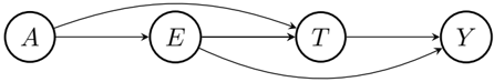
The image displays a simple directed graph (or flowchart) consisting of four circular nodes arranged horizontally from left to right. Each node contains a single uppercase letter. Directed edges, represented by curved arrows, connect the nodes, indicating a one-way flow or relationship between them. The diagram is minimal, with no title, axis labels, or legend.
### Components
* **Nodes:** Four circular nodes, each containing a single letter.
* **Node A:** Positioned at the far left.
* **Node E:** Positioned to the right of A.
* **Node T:** Positioned to the right of E.
* **Node Y:** Positioned at the far right.
* **Edges (Arrows):** Five directed, curved arrows indicating flow or dependency.
* An arrow originates from the right side of Node A and points to the left side of Node E.
* An arrow originates from the top-right of Node A and curves over to point to the top-left of Node T.
* An arrow originates from the right side of Node E and points to the left side of Node T.
* An arrow originates from the bottom-right of Node E and curves under to point to the bottom-left of Node Y.
* An arrow originates from the right side of Node T and points to the left side of Node Y.
### Detailed Analysis
The graph defines a specific set of directional relationships:
1. **A → E:** A direct connection from A to E.
2. **A → T:** A direct connection from A to T, bypassing E.
3. **E → T:** A direct connection from E to T.
4. **E → Y:** A direct connection from E to Y, bypassing T.
5. **T → Y:** A direct connection from T to Y.
The spatial layout is linear and horizontal. The arrows are drawn as smooth curves, with the connections from A to T and from E to Y arcing above and below the central line of nodes, respectively, to avoid overlapping the other arrows.
### Key Observations
* **Multiple Paths:** There are multiple pathways from the start (A) to the end (Y). For example: A → E → T → Y, A → E → Y, and A → T → Y.
* **Bypass Connections:** The diagram includes "shortcut" edges (A→T and E→Y) that skip intermediate nodes in the primary left-to-right sequence.
* **No Cycles:** The graph is acyclic; all arrows point generally from left to right, and no path loops back to an earlier node.
* **Minimalist Design:** The diagram contains only the essential elements (nodes and edges). There is no explanatory text, title, or legend.
### Interpretation
This diagram is an abstract representation of a process, workflow, or dependency network. The letters (A, E, T, Y) are placeholders for specific states, stages, tasks, or components.
* **What it demonstrates:** It shows that the final state `Y` can be reached from `T` and directly from `E`. Similarly, `T` can be reached from `A` and from `E`. This suggests a system with parallel pathways and optional steps.
* **Relationships:** The structure implies that `E` and `T` are intermediate stages, but they are not strictly sequential for all paths. `A` is the sole origin point, and `Y` is the sole terminal point.
* **Potential Meaning:** In a practical context, this could model:
* A software pipeline where some steps can be skipped.
* A decision tree with multiple routes to an outcome.
* A supply chain with alternative sourcing or processing paths.
* A state machine where transitions can occur between non-adjacent states.
The absence of specific labels means the exact domain is undefined, but the topological structure clearly communicates a system with **flexibility, redundancy, and multiple convergent paths** leading to a common endpoint (`Y`).