## Diagram: Octree Expansion and Voxel Insertion
### Overview
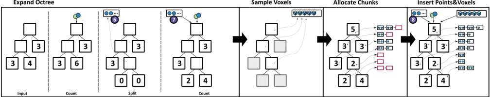
The image illustrates the process of expanding an octree data structure, sampling voxels, allocating chunks, and inserting points and voxels into the tree. The diagram is divided into five stages, each showing the evolution of the octree and associated data.
### Components/Axes
* **Titles:**
* Expand Octree
* Sample Voxels
* Allocate Chunks
* Insert Points&Voxels
* **Labels:**
* Input
* Count
* Split
* Count
* **Octree Representation:** The octree is represented as a tree structure with nodes. Each node is depicted as a square, and the numbers inside the squares indicate a count or identifier.
* **Voxels:** Voxels are represented as small cubes, often grouped together.
* **Chunks:** Chunks are represented as rectangular boxes, sometimes containing voxels.
* **Points:** Points are represented as small circles, often colored blue or green.
* **Arrows:** Arrows indicate the flow of data or operations.
* **Numbers:** Numbers within the nodes of the octree represent counts or identifiers.
### Detailed Analysis
1. **Expand Octree:**
* **Input:** The initial octree consists of a root node and two levels of child nodes. The root node is empty. The first level of children has two nodes with values "3" and "3" respectively. The second level has two nodes with values "3" and "4" respectively.
* **Count:** A point (blue and green circles) is added to the root node. The values of the second level nodes change to "3" and "6" respectively.
* **Split:** A set of points (blue circles) labeled "6" is added to the root node. The octree is split, creating two new nodes with values "0" and "0".
* **Count:** A set of points (blue circles) labeled "7" is added to the root node. The values of the second level nodes change to "2" and "4" respectively.
2. **Sample Voxels:**
* A set of voxels is shown at the top.
* Arrows indicate that voxels are sampled from the octree nodes.
* Some nodes are shaded gray, indicating they have been sampled.
3. **Allocate Chunks:**
* The octree now has nodes with values "5", "3", "3", "3", "2", "2", and "4".
* Arrows indicate that chunks are allocated based on the octree nodes.
* Chunks are represented as rectangular boxes, some containing voxels.
4. **Insert Points&Voxels:**
* The octree structure remains the same as in the "Allocate Chunks" stage.
* A set of points (blue circles) labeled "8" is added to the root node.
* Voxels are inserted into the allocated chunks.
### Key Observations
* The octree expands and splits based on the number of points added.
* Voxels are sampled from the octree nodes.
* Chunks are allocated based on the octree structure.
* Points and voxels are inserted into the allocated chunks.
### Interpretation
The diagram illustrates a process for efficiently storing and managing spatial data using an octree. The octree is dynamically expanded and refined based on the density of points. Voxels are sampled and organized into chunks, which are then associated with the octree nodes. This approach allows for efficient spatial queries and data management. The process demonstrates how an octree can be used to partition space and organize data for applications such as 3D modeling, rendering, and simulation.