## Diagram: Binaural MFMVDR System
### Overview
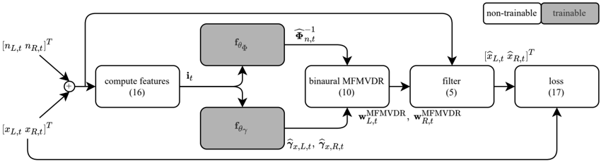
The image is a block diagram illustrating a binaural Minimum Variance Distortionless Response (MFMVDR) system. It shows the flow of data and processing steps, including feature computation, filtering, and loss calculation. The diagram also indicates which components are trainable and non-trainable.
### Components/Axes
* **Input 1:** \[n<sub>L,t</sub> n<sub>R,t</sub>]<sup>T</sup> (Top-left)
* **Input 2:** \[x<sub>L,t</sub> x<sub>R,t</sub>]<sup>T</sup> (Bottom-left)
* **Summation (+):** Combines the two inputs.
* **Compute Features (16):** A rectangular block labeled "compute features (16)". It outputs i<sub>t</sub>.
* **f<sub>θΦ</sub>:** A grayed-out rectangular block labeled "f<sub>θΦ</sub>". It outputs Φ̂<sub>n,t</sub><sup>-1</sup>.
* **f<sub>θγ</sub>:** A grayed-out rectangular block labeled "f<sub>θγ</sub>". It outputs γ̂<sub>x,L,t</sub>, γ̂<sub>x,R,t</sub>.
* **Binaural MFMVDR (10):** A rectangular block labeled "binaural MFMVDR (10)". It receives inputs from "compute features", "f<sub>θΦ</sub>", and "f<sub>θγ</sub>". It outputs w<sup>MFMVDR</sup><sub>L,t</sub>, w<sup>MFMVDR</sup><sub>R,t</sub>.
* **Filter (5):** A rectangular block labeled "filter (5)". It receives input from "binaural MFMVDR". It outputs \[x̂<sub>L,t</sub> x̂<sub>R,t</sub>]<sup>T</sup>.
* **Loss (17):** A rectangular block labeled "loss (17)". It receives input from "filter" and the original input \[x<sub>L,t</sub> x<sub>R,t</sub>]<sup>T</sup>.
* **Feedback Loop:** A feedback loop connects the output of the "filter" block to the "loss" block. Another feedback loop connects the output of the "loss" block to the "f<sub>θγ</sub>" block.
* **Trainability Indicator:** A legend in the top-right corner indicates "non-trainable" (white) and "trainable" (gray).
### Detailed Analysis
1. **Input Stage:** The system takes two inputs, \[n<sub>L,t</sub> n<sub>R,t</sub>]<sup>T</sup> and \[x<sub>L,t</sub> x<sub>R,t</sub>]<sup>T</sup>, which are summed together. These likely represent noise and signal components, respectively, for the left (L) and right (R) channels at time t.
2. **Feature Computation:** The summed signal is fed into the "compute features (16)" block, which calculates relevant features denoted as i<sub>t</sub>.
3. **Parameter Estimation:** The features i<sub>t</sub> are then used by two trainable blocks, "f<sub>θΦ</sub>" and "f<sub>θγ</sub>", to estimate parameters Φ̂<sub>n,t</sub><sup>-1</sup> and γ̂<sub>x,L,t</sub>, γ̂<sub>x,R,t</sub>, respectively.
4. **Binaural MFMVDR Filtering:** The estimated parameters and features are fed into the "binaural MFMVDR (10)" block, which calculates the filter weights w<sup>MFMVDR</sup><sub>L,t</sub> and w<sup>MFMVDR</sup><sub>R,t</sub>.
5. **Filtering:** The calculated filter weights are applied in the "filter (5)" block to produce the estimated signals \[x̂<sub>L,t</sub> x̂<sub>R,t</sub>]<sup>T</sup>.
6. **Loss Calculation:** The estimated signals are compared to the original signal \[x<sub>L,t</sub> x<sub>R,t</sub>]<sup>T</sup> in the "loss (17)" block to calculate a loss value.
7. **Training:** The loss value is used to update the parameters of the trainable blocks "f<sub>θΦ</sub>" and "f<sub>θγ</sub>" via a feedback loop.
### Key Observations
* The diagram illustrates a binaural signal processing system.
* The system uses a Minimum Variance Distortionless Response (MFMVDR) filter.
* The blocks "f<sub>θΦ</sub>" and "f<sub>θγ</sub>" are trainable, while the other blocks are not.
* The system includes feedback loops for training the trainable components.
### Interpretation
The diagram represents a binaural MFMVDR system designed to enhance a target signal in the presence of noise. The system estimates parameters related to the noise and target signal, uses these parameters to calculate filter weights, and applies the filter to the mixed signal. The loss function quantifies the difference between the estimated and original target signals, and this information is used to train the trainable components of the system. The trainable components likely learn to estimate the parameters more accurately, leading to improved signal enhancement performance. The feedback loops are crucial for the system's ability to adapt and improve its performance over time.