## Diagram: Cloud-User Interaction Architecture
### Overview
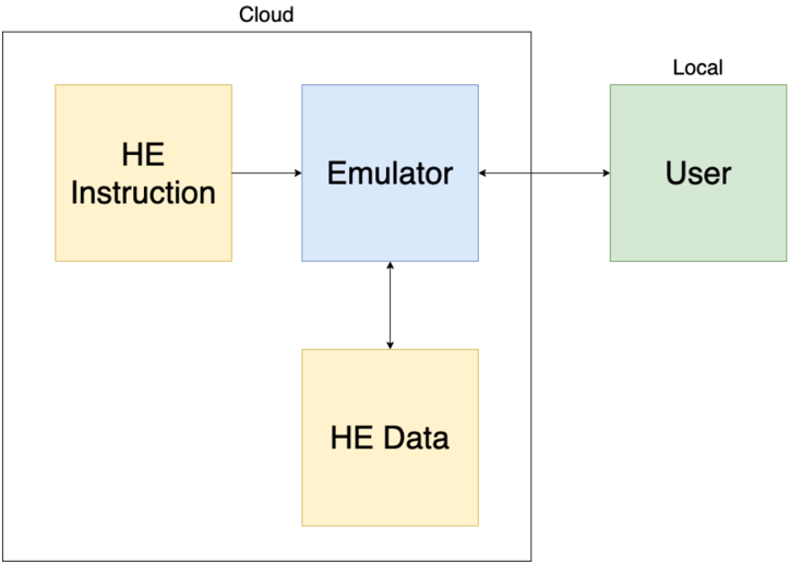
The diagram illustrates a system architecture involving cloud-based components and a local user interface. It depicts bidirectional and unidirectional data flows between four key components: HE Instruction, Emulator, HE Data, and User. The system is divided into two sections: "Cloud" (containing three components) and "Local" (containing one component).
### Components/Axes
1. **Cloud Section** (Left side, orange/blue boxes):
- **HE Instruction** (Orange box): Top-left position
- **Emulator** (Blue box): Center position
- **HE Data** (Orange box): Bottom-center position
2. **Local Section** (Right side, green box):
- **User** (Green box): Right side
3. **Flow Arrows**:
- **Bidirectional**: Between Emulator and HE Data (double-headed arrow)
- **Unidirectional**:
- Cloud → Local: Emulator → User (single-headed arrow)
- Cloud Internal: HE Instruction → Emulator (single-headed arrow)
### Detailed Analysis
- **HE Instruction** (Orange) → **Emulator** (Blue):
- Represents input instructions from cloud-based high-expectation (HE) systems to the emulator.
- **Emulator** (Blue) ↔ **HE Data** (Orange):
- Indicates two-way communication between the emulator and cloud-based HE data storage/retrieval.
- **Emulator** (Blue) → **User** (Green):
- Shows output delivery from the emulator to the local user interface.
### Key Observations
1. **Bidirectional Data Flow**: The emulator maintains continuous interaction with HE Data, suggesting real-time processing or iterative feedback.
2. **Unidirectional User Output**: Final results only flow from the emulator to the user, implying a one-way presentation layer.
3. **Component Isolation**: The Cloud section operates independently of the Local section except through the emulator interface.
### Interpretation
This architecture represents a hybrid cloud-local system where:
- **HE Instruction** acts as a configuration/input module for cloud processing.
- The **Emulator** serves as a central processing unit that:
- Receives instructions from HE systems
- Manages HE Data (possibly for simulation or validation purposes)
- Delivers processed results to end-users
- The **User** component represents the final interface layer, isolated from direct cloud interaction.
The bidirectional flow between Emulator and HE Data suggests a dynamic system where cloud resources are continuously updated or validated during processing. The unidirectional user output emphasizes a controlled delivery mechanism, potentially for security or performance reasons. This design pattern is common in distributed systems requiring secure data handling while maintaining real-time user interaction.