## Diagram: Recurrent Neural Network Cell
### Overview
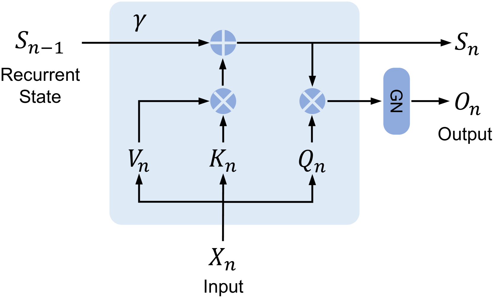
The image is a diagram illustrating the flow of information within a recurrent neural network (RNN) cell. It shows the input, recurrent state, and output, along with the operations performed within the cell.
### Components/Axes
* **Input:** Xn, labeled as "Input" below the variable.
* **Recurrent State (Input):** Sn-1, labeled as "Recurrent State" below the variable.
* **Recurrent State (Output):** Sn
* **Output:** On, labeled as "Output" below the variable.
* **Cell Boundary:** A light blue rounded rectangle encompasses the operations within the cell.
* **Gamma (γ):** Located at the top of the cell.
* **Vn, Kn, Qn:** Intermediate variables within the cell.
* **GN:** A blue rounded rectangle.
* **Plus Symbol (+):** Indicates addition operation.
* **Cross Symbol (X):** Indicates multiplication operation.
* **Arrows:** Indicate the direction of data flow.
### Detailed Analysis
1. **Input Xn:** The input Xn flows upwards and splits into three paths.
* It flows to Vn.
* It flows to Kn.
* It flows to Qn.
2. **Vn, Kn, Qn Interaction:**
* Vn flows upwards and multiplies with Sn-1.
* Kn flows upwards and adds to the result of the multiplication of Vn and Sn-1.
* Qn flows upwards and multiplies with Sn-1.
3. **Recurrent State Update:**
* The result of the addition of Kn and the multiplication of Vn and Sn-1 is added to Gamma (γ).
* The result of the addition of Gamma (γ) and the addition of Kn and the multiplication of Vn and Sn-1 becomes the new recurrent state Sn.
4. **Output Generation:**
* The result of the multiplication of Qn and Sn-1 flows into GN.
* GN outputs On.
### Key Observations
* The diagram illustrates a single time step (n) in an RNN.
* The recurrent state Sn-1 is updated based on the input Xn and the previous state.
* The output On is generated based on the input Xn and the previous state.
* The cell involves multiplication and addition operations.
### Interpretation
The diagram represents a simplified view of a recurrent neural network cell. The input Xn and the previous recurrent state Sn-1 are combined through a series of operations (multiplication and addition) to produce the new recurrent state Sn and the output On. The variables Vn, Kn, and Qn likely represent transformations or projections of the input, while GN represents a gating mechanism or non-linear transformation applied to the output. The Gamma (γ) likely represents a bias term. This architecture allows the network to maintain a memory of past inputs, enabling it to process sequential data effectively.