\n
## Diagram: Recurrent Neural Network Cell
### Overview
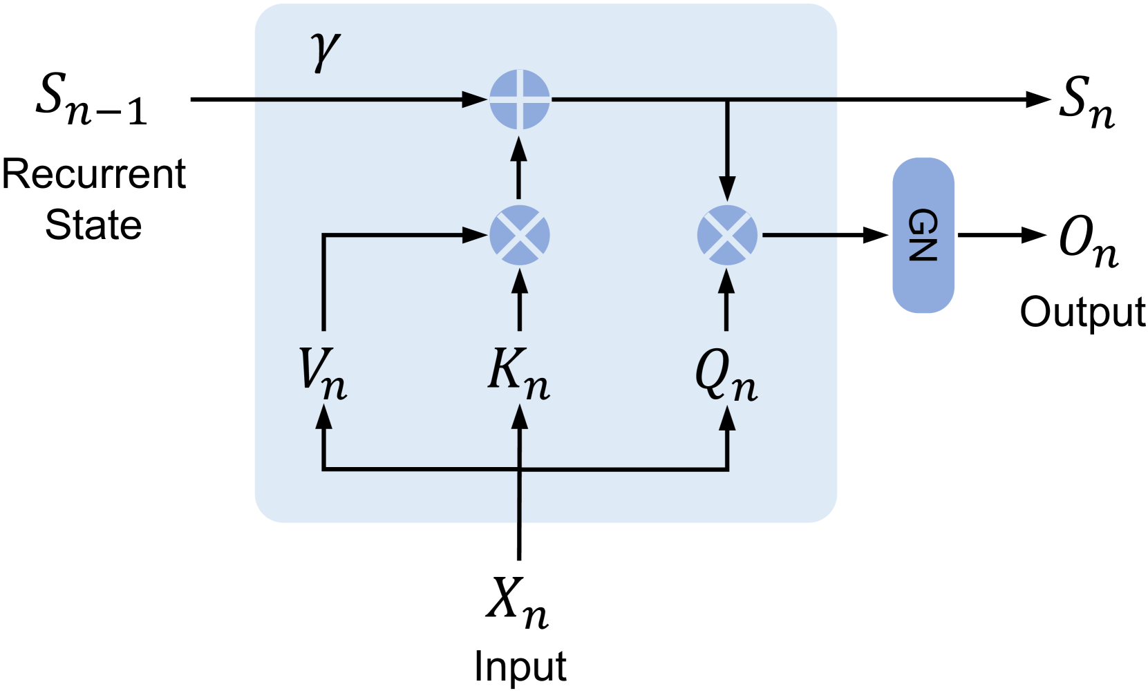
The image depicts a diagram of a recurrent neural network (RNN) cell. It illustrates the flow of information through the cell, showing the input, recurrent state, and output connections. The cell contains three main operations represented by cross-like symbols, and a final output layer represented by a cylinder.
### Components/Axes
The diagram includes the following labeled components:
* **S<sub>n-1</sub>**: Recurrent State (input) - positioned on the left side of the diagram.
* **S<sub>n</sub>**: Recurrent State (output) - positioned on the right side of the diagram.
* **X<sub>n</sub>**: Input - positioned at the bottom of the diagram.
* **O<sub>n</sub>**: Output - positioned on the right side of the diagram.
* **V<sub>n</sub>**: An internal connection within the cell.
* **K<sub>n</sub>**: An internal connection within the cell.
* **Q<sub>n</sub>**: An internal connection within the cell.
* **γ**: A connection from the recurrent state to the first operation.
* **Ω<sub>N</sub>**: A component within the output layer.
The diagram is contained within a light blue rectangular box, representing the RNN cell. The connections between components are represented by arrows.
### Detailed Analysis / Content Details
The diagram shows the following flow of information:
1. **Input (X<sub>n</sub>)** feeds into three operations within the cell (represented by the cross-like symbols).
2. **Recurrent State (S<sub>n-1</sub>)** feeds into the first operation, along with a connection labeled γ.
3. The output of the first operation (V<sub>n</sub>) feeds into the second operation (K<sub>n</sub>).
4. The output of the second operation (K<sub>n</sub>) and the input (X<sub>n</sub>) feed into the third operation (Q<sub>n</sub>).
5. The output of the third operation (Q<sub>n</sub>) feeds into the output layer (Ω<sub>N</sub>), which produces the final **Output (O<sub>n</sub>)**.
6. The output of the first operation (V<sub>n</sub>) also loops back to itself, creating a recurrent connection.
7. The output of the third operation (Q<sub>n</sub>) also feeds into the next recurrent state (S<sub>n</sub>).
The operations within the cell are represented by a cross-like symbol, suggesting a matrix multiplication or similar transformation. The output layer (Ω<sub>N</sub>) is represented by a cylinder, suggesting a non-linear activation function or a projection layer.
### Key Observations
The diagram highlights the core components of an RNN cell: the input, the recurrent state, and the output. The recurrent connection (V<sub>n</sub>) is crucial for maintaining information about past inputs, enabling the network to process sequential data. The diagram does not provide specific numerical values or parameters.
### Interpretation
This diagram illustrates the fundamental building block of a recurrent neural network. The RNN cell processes sequential data by maintaining an internal state (S<sub>n</sub>) that is updated at each time step. The input (X<sub>n</sub>) and the previous state (S<sub>n-1</sub>) are combined to produce the current state (S<sub>n</sub>) and the output (O<sub>n</sub>). The recurrent connection allows the network to "remember" past information, making it suitable for tasks such as natural language processing, time series analysis, and speech recognition. The diagram is a simplified representation of a more complex RNN cell, which may include additional components such as gates and hidden layers. The diagram focuses on the information flow and the key components, rather than the specific mathematical details of the operations.