## Diagram: Recurrent Attention Unit Block Diagram
### Overview
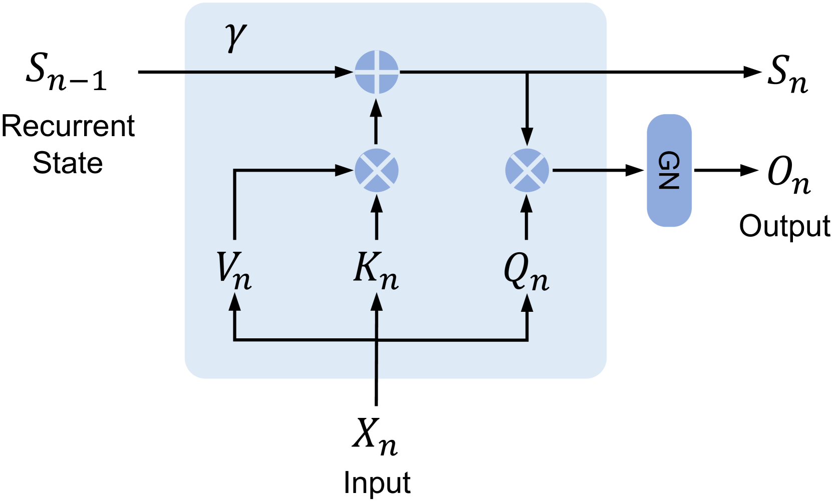
The image displays a technical block diagram of a recurrent neural network component, specifically illustrating a unit that processes an input \(X_n\) and a previous recurrent state \(S_{n-1}\) to produce an updated state \(S_n\) and an output \(O_n\). The diagram uses standard mathematical notation and flow arrows to depict data flow and operations within a defined computational block (light blue rectangle).
### Components/Axes
The diagram is composed of labeled signals, operational nodes, and a processing block. There are no traditional chart axes. The key components are:
**Inputs:**
* **\(S_{n-1}\)**: Labeled "Recurrent State". Positioned at the top-left, entering the main block from the left.
* **\(X_n\)**: Labeled "Input". Positioned at the bottom-center, entering the main block from below.
**Internal Signals (within the light blue block):**
* **\(V_n\)**: Derived from \(X_n\). Positioned in the lower-left quadrant of the block.
* **\(K_n\)**: Derived from \(X_n\). Positioned in the lower-center of the block.
* **\(Q_n\)**: Derived from \(X_n\). Positioned in the lower-right quadrant of the block.
* **\(\gamma\)**: A parameter or scaling factor. Positioned in the top-left area of the block, above the main data path.
**Outputs:**
* **\(S_n\)**: The updated recurrent state. Positioned at the top-right, exiting the main block to the right.
* **\(O_n\)**: Labeled "Output". Positioned at the far right, exiting a separate blue block labeled "GN".
**Operational Nodes:**
* **Addition Node (Circle with +)**: Located on the top data path inside the main block. It receives \(S_{n-1}\) (scaled by \(\gamma\)) and the output of a multiplication node.
* **Multiplication Node 1 (Circle with ×)**: Located in the center-left of the main block. It receives \(V_n\) and \(K_n\) as inputs. Its output feeds into the addition node.
* **Multiplication Node 2 (Circle with ×)**: Located in the center-right of the main block. It receives \(Q_n\) and the updated state signal (post-addition) as inputs. Its output feeds into the "GN" block.
* **GN Block**: A rounded blue rectangle labeled "GN". Positioned to the right of the main block. It receives the output from Multiplication Node 2 and produces the final output \(O_n\).
### Detailed Analysis
**Data Flow and Operations:**
1. **State Update Path:** The previous state \(S_{n-1}\) flows horizontally from the left. It is multiplied by a factor \(\gamma\) (implied by proximity, though no explicit multiplication symbol is shown on that line). Concurrently, the input \(X_n\) is projected into three vectors: \(V_n\), \(K_n\), and \(Q_n\). \(V_n\) and \(K_n\) are combined via a multiplication operation (likely a dot-product or element-wise product). The result of this \(V_n \times K_n\) operation is then added to the scaled previous state (\(\gamma \cdot S_{n-1}\)) to form the new state \(S_n\).
2. **Output Generation Path:** The newly computed state \(S_n\) is tapped and fed into a second multiplication operation along with the query vector \(Q_n\). The result of \(Q_n \times S_n\) is passed through a block labeled "GN" (likely standing for "Group Normalization" or "Gain Normalization") to produce the final output \(O_n\).
**Spatial Grounding:**
* The main computational block is a light blue rectangle occupying the center of the image.
* Inputs enter from the left (\(S_{n-1}\)) and bottom (\(X_n\)).
* Outputs exit to the right (\(S_n\) and \(O_n\)).
* The "GN" block is positioned outside and to the right of the main blue rectangle.
### Key Observations
* The diagram represents a **gated or attention-based recurrent unit**. The structure resembles a linear attention mechanism or a simplified transformer cell unrolled over time step \(n\).
* The operations suggest that the new state \(S_n\) is a function of the previous state and a key-value style interaction (\(V_n \times K_n\)) derived from the current input.
* The output \(O_n\) is generated by attending the current query \(Q_n\) to the *updated* state \(S_n\), followed by normalization.
* The parameter \(\gamma\) likely controls the contribution of the previous state, acting as a forget gate or decay factor.
* The use of distinct \(V\), \(K\), and \(Q\) projections from a single input \(X_n\) is a hallmark of attention mechanisms.
### Interpretation
This diagram illustrates the core computational logic of a recurrent layer that incorporates attention-like mechanisms. It is designed to process sequential data (\(X_n\)) while maintaining a memory state (\(S_{n-1}\)).
* **Function:** The unit performs two main functions: (1) **State Memory Update**, where it integrates new information from the input (via \(V_n\) and \(K_n\)) with its existing memory, and (2) **Contextual Output Generation**, where it produces an output based on a query (\(Q_n\)) applied to its current memory state.
* **Relationships:** The input \(X_n\) is central, being transformed into three distinct functional roles (Value, Key, Query). The state \(S_n\) serves as a dynamic memory that is both an output for the next time step and a context for generating the current output \(O_n\).
* **Notable Design:** The flow where the output \(O_n\) is derived from \(Q_n\) interacting with the *updated* state \(S_n\) (rather than the previous state \(S_{n-1}\)) is significant. This means the output for time step \(n\) immediately reflects the newly integrated information from input \(X_n\), allowing for very responsive sequence processing. The "GN" block suggests a normalization step is critical for stabilizing the output activations.
* **Potential Application:** This architecture is characteristic of modern recurrent units like **Linear Transformers**, **Recurrent Memory Networks**, or **Gated Attention Cells**, which aim to combine the parallelizability of feed-forward models with the memory capabilities of RNNs.