## Diagram: Coordinate System with Target and Positioned Crosses
### Overview
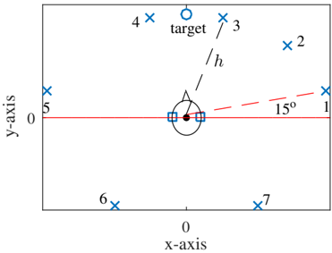
The image depicts a 2D Cartesian coordinate system with labeled axes (x-axis and y-axis). A central "target" is marked at the origin (0,0) with a blue circle. Seven blue crosses (labeled 1–7) are positioned at specific coordinates along the x-axis. A dashed red line connects the target to cross 1, forming a 15° angle with the x-axis.
### Components/Axes
- **Axes**:
- **x-axis**: Labeled "x-axis" with numerical markers at -7, -6, -5, 0, 1, 2, 3, 4, 5, 6, 7.
- **y-axis**: Labeled "y-axis" with a single visible marker at 0.
- **Target**: Blue circle centered at (0,0), labeled "target."
- **Crosses**:
- **Cross 1**: Positioned at (1,0), connected to the target via a dashed red line.
- **Cross 2**: Positioned at (3,0).
- **Cross 3**: Positioned at (4,0).
- **Cross 4**: Positioned at (5,0).
- **Cross 5**: Positioned at (-5,0).
- **Cross 6**: Positioned at (-6,0).
- **Cross 7**: Positioned at (-7,0).
- **Angle**: Dashed red line from target to cross 1 forms a 15° angle with the x-axis.
### Detailed Analysis
- **Cross Positions**:
- Crosses 1–4 are on the positive x-axis at distances 1, 3, 4, and 5 units from the origin.
- Crosses 5–7 are on the negative x-axis at distances 5, 6, and 7 units from the origin.
- **Dashed Line**: The red dashed line from the target to cross 1 creates a 15° angle with the x-axis, suggesting a directional relationship between the target and cross 1.
- **Symmetry**: Crosses 1 and 5 are equidistant from the origin (1 and 5 units), but cross 1 is closer. Crosses 2 and 4 are asymmetrically placed (3 vs. 5 units).
### Key Observations
1. The target is centrally located at the origin, while crosses are distributed asymmetrically along the x-axis.
2. Cross 1 is the only cross connected to the target via a dashed line, emphasizing its significance.
3. The 15° angle between the dashed line and the x-axis may indicate a directional or angular relationship (e.g., orientation, trajectory).
4. Crosses 5–7 extend further along the negative x-axis than crosses 1–4 on the positive side.
### Interpretation
- The diagram likely represents a spatial analysis where the target (origin) is a reference point, and crosses denote positions of interest.
- The 15° angle suggests a specific directional focus (e.g., alignment, measurement) between the target and cross 1.
- The asymmetry in cross placement (e.g., cross 5 at -5 vs. cross 1 at +1) may imply uneven distribution or prioritization of certain positions.
- The absence of a y-axis scale beyond 0 suggests the focus is strictly on x-axis positioning, with no vertical displacement for the crosses.
## Additional Notes
- **Language**: All text is in English.
- **Missing Elements**: No legend, colorbar, or additional annotations beyond axis labels and cross identifiers.
- **Uncertainty**: Exact y-axis scaling is unclear (only 0 is labeled). The 15° angle is explicitly stated but lacks a reference for measurement precision.