## Diagram: Simple Neural Network Model and System Memory Allocation
### Overview
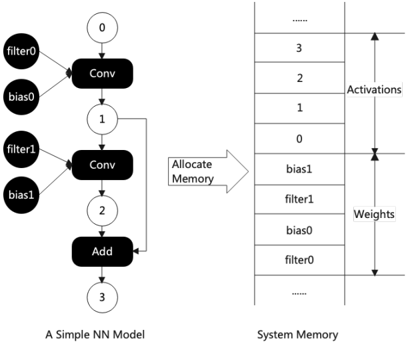
The image depicts a simplified neural network (NN) model on the left and its corresponding system memory allocation on the right. The left diagram illustrates the computational flow of the NN, while the right diagram shows how parameters (filters, biases) and activations are stored in memory.
### Components/Axes
#### Left Diagram (Neural Network Model):
- **Components**:
- Two convolutional layers (`Conv`), labeled `Conv0` and `Conv1`.
- Two addition operations (`Add`), labeled `Add`.
- Nodes numbered `0`, `1`, `2`, and `3`, representing intermediate outputs.
- **Connections**:
- `Conv0` receives inputs from `filter0` and `bias0`, outputs to node `0`.
- `Conv1` receives inputs from `filter1` and `bias1`, outputs to node `1`.
- `Add` combines outputs from node `1` and node `2` (unlabeled in the diagram but implied by the flow), producing node `3`.
#### Right Diagram (System Memory):
- **Structure**:
- A vertical table with two columns: `Activations` (top) and `Weights` (bottom).
- Rows are numbered `3` (top) to `0` (bottom) for `Activations`, and `0` (top) to `3` (bottom) for `Weights`.
- **Labels**:
- `Activations` column lists: `bias1`, `filter1`, `bias0`, `filter0`, and `...` (truncated).
- `Weights` column lists: `filter0`, `bias0`, `filter1`, `bias1`, and `...` (truncated).
### Detailed Analysis
#### Left Diagram:
1. **Convolutional Layers**:
- `Conv0` and `Conv1` represent feature extraction stages. Each `Conv` layer has associated `filter` and `bias` parameters.
- Filters (`filter0`, `filter1`) and biases (`bias0`, `bias1`) are stored in memory (right diagram).
2. **Add Operation**:
- Combines outputs from `Conv1` (node `1`) and an intermediate node (`2`), producing the final activation (node `3`).
#### Right Diagram:
1. **Memory Allocation**:
- **Activations**: Stored in descending order (`3` to `0`), starting with `bias1` and ending with `filter0`.
- **Weights**: Stored in ascending order (`0` to `3`), starting with `filter0` and ending with `bias1`.
- The `...` indicates additional parameters not shown in the diagram.
### Key Observations
1. **Memory Layout**:
- Activations and weights are stored in separate memory regions, with distinct ordering.
- Activations follow a reverse numerical order (`3` to `0`), while weights follow a forward numerical order (`0` to `3`).
2. **Component Relationships**:
- Each `Conv` layer’s `filter` and `bias` are stored sequentially in memory (e.g., `filter0`, `bias0` for `Conv0`).
- The `Add` operation’s output (node `3`) corresponds to the topmost activation (`bias1`) in memory.
### Interpretation
1. **Computational Flow vs. Memory Storage**:
- The NN’s forward pass (left) processes data through `Conv` layers and an `Add` operation, while the right diagram shows how parameters and intermediate results are stored for efficient access.
- The memory layout suggests a design optimized for sequential data retrieval, aligning with the NN’s computation steps.
2. **Significance of Ordering**:
- The reverse ordering of activations (`3` to `0`) may reflect the backward flow of gradients during backpropagation, though this is speculative without explicit labels.
- Weights are stored in the order they are used during forward propagation (`filter0`, `bias0`, etc.).
3. **Implications for Efficiency**:
- The memory allocation minimizes redundant data access by organizing parameters and activations in a predictable sequence.
- The diagram highlights the importance of memory hierarchy in deep learning systems, where parameter storage and activation caching are critical for performance.
### Conclusion
The diagram illustrates the interplay between a neural network’s computational graph and its memory architecture. The structured memory allocation ensures that parameters and activations are stored in a way that aligns with the NN’s execution flow, optimizing both speed and resource utilization. This design is foundational for efficient inference and training in deep learning systems.