\n
## Diagram: Network Transformation with Beta Parameter
### Overview
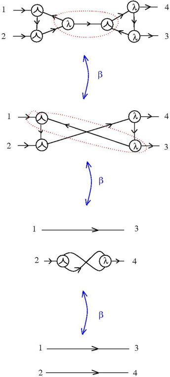
The image depicts a series of diagrams illustrating a transformation of a network structure. The diagrams are arranged vertically, showing a progression of changes. Each diagram represents a network with nodes and directed edges. A curved blue arrow labeled "β" appears between the first two and second two diagrams, indicating a transformation process. The diagrams show nodes labeled 1, 2, 3, and 4, and nodes with a symbol resembling a "Y" and the Greek letter lambda (λ).
### Components/Axes
The diagrams consist of:
* **Nodes:** Represented by circles. Some nodes are labeled with numbers (1, 2, 3, 4) and others with symbols (Y-shaped node and λ).
* **Directed Edges:** Arrows indicating the direction of connections between nodes. Edges are shown in black and red.
* **Transformation Arrow:** A curved blue arrow labeled "β" indicating a transformation between network states.
* **Labels:** Numbers 1, 2, 3, and 4 are used to label input and output nodes.
### Detailed Analysis or Content Details
**Diagram 1 (Top):**
* Input nodes: 1 and 2.
* Node 1 connects to a Y-shaped node.
* Node 2 connects to a Y-shaped node.
* Both Y-shaped nodes connect to λ nodes.
* The λ nodes connect to output nodes 4 and 3 respectively.
* There are dotted lines connecting the Y-shaped nodes to the λ nodes.
**Diagram 2 (Middle):**
* Input nodes: 1 and 2.
* Node 1 connects directly to a λ node.
* Node 2 connects directly to a λ node.
* The λ nodes connect to output nodes 4 and 3 respectively.
* Edges are now solid black and red.
* The Y-shaped nodes have disappeared.
**Diagram 3 (Second from Bottom):**
* Input nodes: 1 and 2.
* Node 1 connects directly to output node 3.
* Node 2 connects directly to a Y-shaped node, which connects to λ node, which connects to output node 4.
**Diagram 4 (Bottom):**
* Input nodes: 1 and 2.
* Node 1 connects directly to output node 3.
* Node 2 connects directly to output node 4.
### Key Observations
* The network simplifies with each transformation step.
* The Y-shaped nodes and dotted lines disappear in the second diagram.
* The transformation "β" appears to reduce the complexity of the network.
* The final diagram shows a direct connection between input and output nodes.
### Interpretation
The diagrams illustrate a process of network simplification or reduction. The parameter "β" likely represents an operation or condition that causes the network to evolve from a more complex state (Diagram 1) to a simpler state (Diagram 4). The initial network (Diagram 1) appears to have intermediate processing stages (Y-shaped and λ nodes) that are eliminated through the transformation "β". The final network (Diagram 4) represents a direct mapping between inputs and outputs, suggesting that the intermediate processing stages are no longer necessary or have been optimized away. The change in edge color from dotted to solid in Diagram 2 could indicate a strengthening or activation of connections. The diagrams could represent a simplification of a computational model, a reduction in the number of layers in a neural network, or a similar process in a complex system. The diagrams are abstract and do not provide specific quantitative data, but they demonstrate a clear trend towards simplification and direct mapping.