## Block Diagram: Minitaur Core Architecture
### Overview
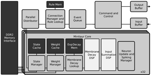
The image is a block diagram illustrating the architecture of the Minitaur Core, a system likely designed for neural network processing or similar computational tasks. The diagram shows the flow of data and control signals between various components, including memory interfaces, rule management, parallel distribution, and individual processing units within the core.
### Components/Axes
The diagram consists of several interconnected blocks, each representing a functional unit. The major components are:
* **DDR2 Memory Interface:** Located on the left side, this block represents the interface to external DDR2 memory.
* **Rule Mem:** A block at the top, likely related to rule storage or processing.
* **Parallel Distributor:** A block to the right of the DDR2 Memory Interface, responsible for distributing data in parallel.
* **Connection Manager and Rule Lookup:** A block to the right of the Parallel Distributor, likely managing connections and looking up rules.
* **Event Queue:** A block to the right of the Connection Manager and Rule Lookup, likely queuing events.
* **Command and Control:** A large block at the top-right, responsible for overall command and control.
* **Input Buffer:** Located at the right side, this block represents the input buffer.
* **Output Buffer:** Located at the right side, this block represents the output buffer.
* **Minitaur Core:** A large block in the center, containing several sub-components:
* **State Cache:** A block in the Minitaur Core, likely caching state information.
* **Weight Cache:** A block in the Minitaur Core, likely caching weight information.
* **Exp Decay Mem:** A block in the Minitaur Core, likely related to exponential decay memory.
* **Membrane Decay DSP:** A block in the Minitaur Core, likely a digital signal processor for membrane decay calculations.
* **Input Summation DSP:** A block in the Minitaur Core, likely a digital signal processor for input summation.
* **Neuron Update and Spiking Manager:** A block in the Minitaur Core, responsible for updating neuron states and managing spiking behavior.
* **State Manager:** A block in the Minitaur Core, likely managing state information.
* **Weight Manager:** A block in the Minitaur Core, likely managing weight information.
* **Membrane Decay Lookup:** A block in the Minitaur Core, likely related to membrane decay lookup.
### Detailed Analysis or Content Details
* **DDR2 Memory Interface:** The DDR2 Memory Interface is connected to the Minitaur Core via multiple lines, suggesting parallel data transfer.
* **Minitaur Core:** The Minitaur Core is replicated "x32" times, as indicated in the bottom-right corner, suggesting a parallel processing architecture.
* **Color Coding:** The blocks are shaded in different grayscales. The State Cache, Weight Cache, State Manager, and Weight Manager are darker than the other blocks in the Minitaur Core. The Input Summation DSP and Membrane Decay DSP are lighter than the other blocks in the Minitaur Core.
### Key Observations
* The diagram illustrates a complex system with multiple interconnected components.
* The Minitaur Core appears to be the central processing unit, with dedicated modules for memory management, rule processing, and neuron-specific calculations.
* The parallel architecture (x32 replication) suggests a design optimized for high-throughput processing.
### Interpretation
The block diagram represents a specialized hardware architecture, likely designed for accelerating neural network computations or similar tasks. The presence of dedicated modules for state management, weight caching, and membrane decay calculations suggests a focus on simulating or processing spiking neural networks. The parallel architecture and the DDR2 memory interface indicate a design optimized for high-performance and large-scale data processing. The different shades of gray may indicate different levels of activity or different types of processing.