\n
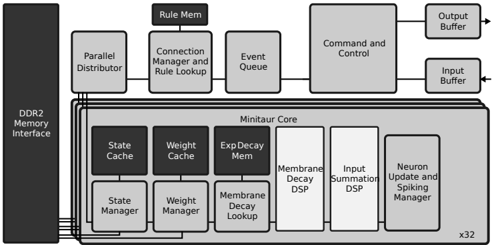
## Diagram: Neuromorphic Chip Architecture
### Overview
The image depicts a block diagram of a neuromorphic chip architecture. It illustrates the various components and their interconnections, focusing on the "Minitaur Core" and its surrounding modules. The diagram is grayscale and appears to be a technical illustration from a research paper or engineering document.
### Components/Axes
The diagram consists of the following key components:
* **DDR2 Memory Interface:** Located on the left side of the diagram.
* **Parallel Distributor:** Connected to the DDR2 Memory Interface.
* **Connection Manager and Rule Lookup:** Connected to the Parallel Distributor.
* **Event Queue:** Connected to the Connection Manager and Rule Lookup.
* **Command and Control:** Connected to the Event Queue.
* **Output Buffer:** Connected to the Command and Control.
* **Input Buffer:** Connected to the Command and Control.
* **Rule Mem:** Connected to the Connection Manager and Rule Lookup.
* **Minitaur Core:** A large block containing several sub-components.
* **State Cache:** Within the Minitaur Core.
* **Weight Cache:** Within the Minitaur Core.
* **Exp Decay Mem:** Within the Minitaur Core.
* **Membrane Decay DSP:** Within the Minitaur Core.
* **Input Summation DSP:** Within the Minitaur Core.
* **Neuron Update and Spiking Manager:** Within the Minitaur Core.
* **State Manager:** Below the State Cache.
* **Weight Manager:** Below the Weight Cache.
* **Membrane Decay Lookup:** Below the Exp Decay Mem.
* **x32:** Located at the bottom-right corner, indicating the Minitaur Core is replicated 32 times.
There are no axes or scales in this diagram. It is a schematic representation of the chip's architecture.
### Detailed Analysis or Content Details
The diagram shows a data flow from the DDR2 Memory Interface through the Parallel Distributor, Connection Manager, Event Queue, and Command and Control, ultimately leading to the Input and Output Buffers. The Minitaur Core is the central processing unit, with its internal components handling state, weights, exponential decay, membrane potential, input summation, and neuron updates.
The Minitaur Core is structured with a cache/manager pair for State, Weight, and Membrane Decay. The DSP blocks handle signal processing related to membrane decay and input summation. The Neuron Update and Spiking Manager is responsible for the core neuronal computation.
The "x32" label indicates that the Minitaur Core is replicated 32 times within the chip, suggesting a massively parallel architecture.
### Key Observations
The architecture emphasizes parallel processing and event-driven computation. The separation of connection management and rule lookup suggests a flexible and configurable system. The presence of dedicated hardware for exponential decay and input summation indicates optimization for neuromorphic algorithms. The DDR2 interface suggests this is an older design.
### Interpretation
This diagram represents a neuromorphic computing system designed to mimic the structure and function of the biological brain. The Minitaur Core is the fundamental building block, and its replication suggests a scalable architecture. The data flow indicates an event-driven approach, where computations are triggered by incoming events rather than a fixed clock cycle. The use of specialized hardware components (DSP blocks, dedicated memory) suggests an attempt to optimize performance for specific neuromorphic algorithms. The architecture is likely designed for low-power, high-throughput processing of sensory data or other complex tasks. The DDR2 interface suggests this is an older design, likely from the early 2000s. The diagram provides a high-level overview of the chip's architecture and does not include detailed information about the specific algorithms or implementation details.