TECHNICAL ASSET FINGERPRINT
6f3ccde79bc2c8c355ef44a8
Click to view fullscreen
Press ESC or click to close
FOUND IN PAPERS
EXPERT: healer-alpha-free VERSION 1
RUNTIME: free/openrouter/healer-alpha
INTEL_VERIFIED
## System Architecture Diagram: Minitaur Core
### Overview
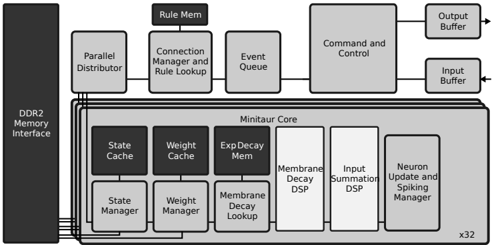
This image is a technical block diagram illustrating the architecture of a computing system centered around a "Minitaur Core." The diagram shows the interconnection between a main memory interface, several management and control units, and the internal components of the core itself. The layout is hierarchical, with the core being the largest and most complex component.
### Components/Axes
The diagram is composed of labeled rectangular blocks connected by lines and arrows indicating data/control flow. There are no traditional chart axes. The primary components are:
**1. Left Column (Memory Interface):**
* **DDR2 Memory Interface:** A tall, vertical block on the far left, spanning the height of the diagram. It serves as the primary memory connection point.
**2. Top Row (System Management & Control):**
* **Parallel Distributor:** Positioned to the right of the DDR2 interface, connected to it.
* **Connection Manager and Rule Lookup:** To the right of the Parallel Distributor. A smaller block labeled **Rule Mem** sits directly above it.
* **Event Queue:** To the right of the Connection Manager.
* **Command and Control:** A large block to the right of the Event Queue.
* **Output Buffer:** A small block to the top-right of Command and Control, with an arrow pointing out (to the right).
* **Input Buffer:** A small block below the Output Buffer, with an arrow pointing in (from the right).
**3. Central Block (Minitaur Core):**
* **Minitaur Core:** The largest block, occupying the lower-center and right portion of the diagram. It contains several internal sub-components arranged in two rows.
* **Internal Components (Top Row within Core):**
* State Cache
* Weight Cache
* Exp Decay Mem
* **Internal Components (Bottom Row within Core):**
* State Manager
* Weight Manager
* Membrane Decay Lookup
* Membrane Decay DSP
* Input Summation DSP
* Neuron Update and Spiking Manager
* **Replication Indicator:** The text **x32** is located at the bottom-right corner of the Minitaur Core block, suggesting this core architecture is replicated 32 times.
**4. Connections:**
* Lines connect the **DDR2 Memory Interface** to the **Parallel Distributor**, **State Cache**, **Weight Cache**, and **Exp Decay Mem**.
* A line connects the **Parallel Distributor** to the **Connection Manager and Rule Lookup**.
* A line connects the **Connection Manager and Rule Lookup** to the **Event Queue**.
* A line connects the **Event Queue** to the **Command and Control** unit.
* Lines connect the **Command and Control** unit to the **Output Buffer** and **Input Buffer**.
* Internal connections within the **Minitaur Core** are implied by the proximity and arrangement of its sub-components, though explicit internal lines are not drawn.
### Detailed Analysis
The diagram details a specialized computing architecture, likely for neuromorphic or parallel processing tasks.
* **Memory Hierarchy:** The system interfaces with external DDR2 memory. Data is distributed via a **Parallel Distributor** and cached locally within the Minitaur Core using dedicated **State Cache**, **Weight Cache**, and **Exp Decay Mem** (Exponential Decay Memory) blocks.
* **Management Layers:** There is a clear separation of concerns:
* **Rule Management:** The **Connection Manager and Rule Lookup** (supported by **Rule Mem**) handles connectivity and rule-based processing.
* **Task Scheduling:** The **Event Queue** manages the flow of operations.
* **Central Control:** The **Command and Control** unit orchestrates the system and manages I/O via dedicated buffers.
* **Core Processing Pipeline (Minitaur Core):** The core's internal blocks suggest a pipeline for neural network-like computation:
1. **State/Weight Management:** **State Manager** and **Weight Manager** handle the core's dynamic parameters.
2. **Decay Mechanisms:** **Membrane Decay Lookup** and **Membrane Decay DSP** (Digital Signal Processor) implement temporal dynamics, likely simulating neuronal membrane potential decay.
3. **Computation:** **Input Summation DSP** aggregates inputs.
4. **Output Generation:** **Neuron Update and Spiking Manager** computes the final state and generates output "spikes" or events.
* **Scalability:** The **x32** notation indicates the entire Minitaur Core is a modular unit, and 32 instances of it operate in parallel within this system.
### Key Observations
1. **Specialized DSPs:** The use of dedicated DSPs for "Membrane Decay" and "Input Summation" highlights that these are computationally intensive, fixed-function operations critical to the architecture's purpose.
2. **Explicit Decay Memory:** The presence of both **Exp Decay Mem** (a memory block) and **Membrane Decay Lookup/DSP** (processing blocks) suggests a sophisticated, multi-level approach to managing temporal decay functions.
3. **Rule-Centric Design:** The prominent placement of **Connection Manager and Rule Lookup** with its own dedicated **Rule Mem** indicates that rule-based processing is a fundamental, first-class operation in this architecture, not just an afterthought.
4. **Clear I/O Path:** The system has a well-defined path for external interaction: data enters via the **Input Buffer**, is processed by **Command and Control**, and results exit via the **Output Buffer**.
### Interpretation
This diagram depicts the architecture of a **massively parallel, neuromorphic-inspired processing system**. The "Minitaur Core" is a self-contained processing element designed to simulate neuronal dynamics, featuring explicit hardware for managing state, weights, and exponential decay functions—key components of spiking neural networks.
The **x32** replication signifies a scalable design where many such cores work in concert, likely to achieve high throughput for parallel workloads. The **Parallel Distributor** and **Connection Manager** are crucial for routing data and managing the complex, potentially dynamic connectivity between these cores or between cores and memory.
The separation of **Rule Mem** and **Rule Lookup** from the main data caches implies that the system's behavior is governed by a set of programmable rules, making it a **configurable architecture** rather than a fixed-function one. This could be used for applications like real-time pattern recognition, sensory processing, or complex system simulation where parallel, event-driven computation with temporal dynamics is essential. The overall design prioritizes parallelism, dedicated hardware for critical operations, and explicit management of temporal (time-based) phenomena.
DECODING INTELLIGENCE...