\n
## Diagram: Neural Network with Consistency Optimization and Abduction
### Overview
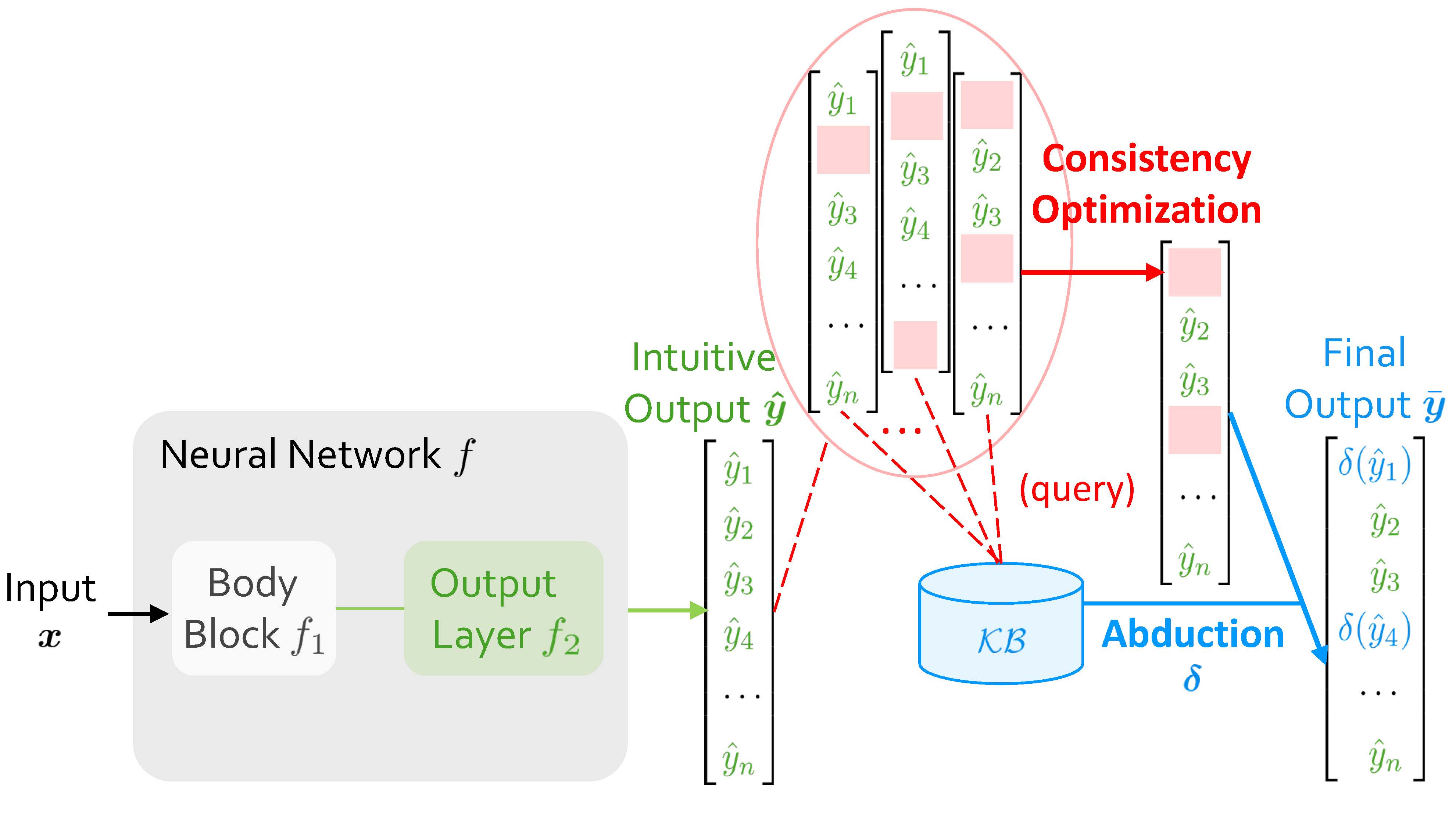
The image is a diagram illustrating a neural network architecture that incorporates consistency optimization and abduction. The diagram shows the flow of data from the input through the neural network, the intuitive output, the consistency optimization process, the knowledge base query, the abduction process, and the final output.
### Components/Axes
* **Neural Network f:** A gray rounded rectangle containing two blocks:
* **Body Block f1:** A light green rounded rectangle.
* **Output Layer f2:** A light green rounded rectangle.
* **Input x:** Located to the left of the Neural Network.
* **Intuitive Output ŷ:** A column vector labeled "Intuitive Output ŷ" containing elements ŷ1, ŷ2, ŷ3, ŷ4, ..., ŷn.
* **Consistency Optimization:** An area enclosed by a light red oval, containing three column vectors similar to the "Intuitive Output ŷ" vector. Some elements within these vectors are highlighted in light red.
* **KB:** A light blue cylinder representing a knowledge base. Labeled "KB".
* **(query):** Text label above the KB cylinder.
* **Abduction δ:** A blue arrow pointing from the KB to the "Final Output ȳ" vector, labeled "Abduction δ".
* **Final Output ȳ:** A column vector labeled "Final Output ȳ" containing elements δ(ŷ1), ŷ2, ŷ3, δ(ŷ4), ..., ŷn.
### Detailed Analysis
* **Input x** flows into the **Neural Network f**.
* The Neural Network consists of a **Body Block f1** and an **Output Layer f2**.
* The output of the Neural Network is the **Intuitive Output ŷ**, represented as a column vector.
* The **Consistency Optimization** process involves multiple column vectors, with some elements highlighted in light red. A red arrow points from the consistency optimization area to a column vector.
* Dashed red lines connect the "Intuitive Output ŷ" vector and the column vectors within the "Consistency Optimization" area to the **KB** (Knowledge Base).
* The **KB** is queried, and the **Abduction δ** process generates the **Final Output ȳ**.
* The "Final Output ȳ" vector contains elements that are either ŷi or δ(ŷi), where δ represents the abduction operation.
### Key Observations
* The diagram illustrates a process where the initial output of a neural network is refined using consistency optimization and abduction with the help of a knowledge base.
* The light red highlights in the "Consistency Optimization" area likely indicate elements that are being adjusted or corrected.
* The abduction process seems to selectively modify certain elements of the output vector based on information from the knowledge base.
### Interpretation
The diagram depicts a neural network architecture that integrates reasoning and knowledge to improve the quality of its output. The "Intuitive Output ŷ" represents the raw output of the neural network, which may contain inconsistencies or errors. The "Consistency Optimization" step attempts to refine this output by enforcing certain constraints or rules. The "KB" (Knowledge Base) provides external knowledge that can be used to further improve the output through "Abduction δ". Abduction is a form of logical inference that seeks to find the best explanation for a set of observations. In this context, it likely involves using the knowledge base to infer the most plausible values for certain elements of the output vector. The "Final Output ȳ" represents the refined output, which is expected to be more accurate and consistent than the initial output. This architecture is useful in applications where the neural network's output needs to be reliable and interpretable, such as in decision-making or diagnosis.