\n
## Diagram: Parallelogram Representation of Vector Addition
### Overview
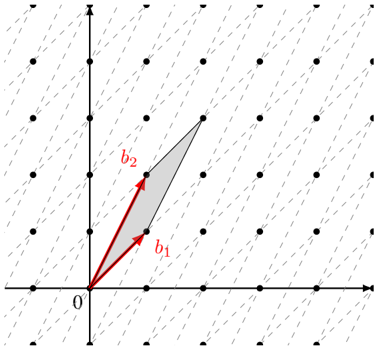
The image depicts a parallelogram constructed from two vectors, `b1` and `b2`, originating from the origin (labeled '0'). The parallelogram visually represents the vector addition of `b1` and `b2`. The background is a grid of dots.
### Components/Axes
* **Axes:** Two perpendicular axes are present. The horizontal axis is not labeled, but is implied to be the x-axis. The vertical axis is also not labeled, but is implied to be the y-axis. Both axes have tick marks indicating a regular scale, but the scale is not numerically defined.
* **Origin:** The origin is clearly marked with the label '0'.
* **Vectors:** Two vectors are labeled:
* `b1`: A red vector originating from the origin and pointing diagonally upwards and to the right.
* `b2`: A red vector originating from the origin and pointing diagonally upwards and to the left.
* **Parallelogram:** A shaded parallelogram is formed by the vectors `b1` and `b2`.
* **Grid:** A grid of dots fills the background, providing a visual reference for scale and position.
### Detailed Analysis
The diagram illustrates the geometric interpretation of vector addition. The parallelogram is constructed such that:
* `b1` starts at the origin and extends to a point.
* `b2` starts at the origin and extends to another point.
* The fourth vertex of the parallelogram (opposite the origin) represents the resultant vector `b1 + b2`.
The vectors `b1` and `b2` are approximately equal in magnitude, but point in different directions. The angle between `b1` and `b2` appears to be approximately 60-90 degrees.
Without a defined scale on the axes, precise numerical values for the components of `b1` and `b2` cannot be determined. However, we can qualitatively describe their direction.
### Key Observations
* The diagram emphasizes the graphical representation of vector addition.
* The parallelogram visually demonstrates that the resultant vector (the diagonal from the origin) is the sum of the two original vectors.
* The grid provides a visual reference for the relative magnitudes and directions of the vectors.
### Interpretation
The diagram demonstrates the parallelogram rule for vector addition. This rule states that the sum of two vectors can be found by constructing a parallelogram with the vectors as adjacent sides. The diagonal of the parallelogram, starting from the common origin of the vectors, represents the resultant vector. This is a fundamental concept in linear algebra and physics, used to represent and manipulate quantities that have both magnitude and direction, such as force, velocity, and displacement. The diagram is a visual aid for understanding this concept, allowing for a qualitative grasp of how vectors combine. The absence of numerical values suggests the diagram is intended to convey the *principle* of vector addition rather than specific calculations.