TECHNICAL ASSET FINGERPRINT
730e7bcfc853d6204ee4d09b
Click to view fullscreen
Press ESC or click to close
FOUND IN PAPERS
EXPERT: healer-alpha-free VERSION 1
RUNTIME: free/openrouter/healer-alpha
INTEL_VERIFIED
## Diagram: System Architecture with Modules, Sensor, and Memory
### Overview
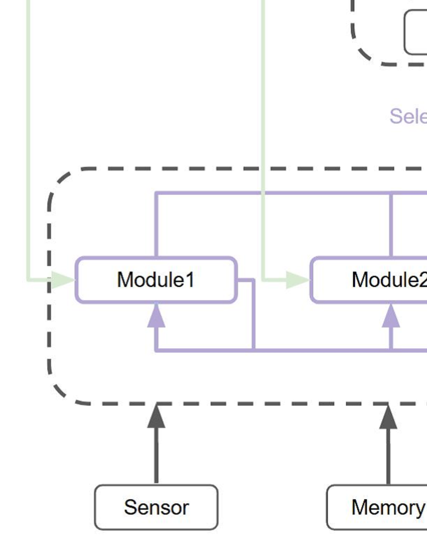
The image displays a partial technical diagram illustrating a system architecture. It shows a central processing or functional unit enclosed within a dashed boundary, containing two primary modules. External components, specifically a "Sensor" and "Memory," provide inputs to this unit. The diagram uses color-coded lines and arrows to indicate different types of data or control flow.
### Components/Axes
The diagram is composed of the following labeled components and connecting lines:
**Components (Boxes):**
1. **Module1**: A rectangular box with rounded corners, outlined in purple. Located inside the dashed boundary, on the left side.
2. **Module2**: A rectangular box with rounded corners, outlined in purple. Located inside the dashed boundary, to the right of Module1.
3. **Sensor**: A rectangular box with rounded corners, outlined in black. Positioned below the dashed boundary, on the left.
4. **Memory**: A rectangular box with rounded corners, outlined in black. Positioned below the dashed boundary, on the right.
5. **Dashed Boundary**: A large, dashed, dark gray line forming a rounded rectangle that encloses Module1 and Module2. This likely represents a subsystem, processor, or integrated circuit boundary.
6. **Partial Element (Top Right)**: A dashed, dark gray outline of a rounded rectangle is partially visible in the top-right corner. Inside it, a solid black outline of a smaller rectangle is also partially visible. Adjacent to this, the purple text "Sele" is visible, which is likely the beginning of a word like "Selector" or "Selection."
**Connections (Lines & Arrows):**
* **Green Lines/Arrows**: Two light green lines with arrowheads enter the dashed boundary from the top. One points directly into the left side of **Module1**. The other points into the left side of **Module2**. These represent external input or control signals.
* **Purple Lines/Arrows**: A network of solid purple lines connects the modules internally.
* A line originates from the top of **Module1**, travels right, and connects to the top of **Module2**.
* A line originates from the bottom of **Module2**, travels left, and connects to the bottom of **Module1**.
* A line originates from the bottom of **Module1**, travels down, then right, then up to connect to the bottom of **Module2**.
* These lines have arrowheads pointing *into* the modules at their connection points, indicating data or signal flow into the modules from this internal bus or network.
* **Black Lines/Arrows**: Two solid black lines with arrowheads point vertically upward.
* One originates from the top of the **Sensor** box and points to the bottom edge of the dashed boundary, directly below Module1.
* The other originates from the top of the **Memory** box and points to the bottom edge of the dashed boundary, directly below Module2.
### Detailed Analysis
**Spatial Layout and Flow:**
* The **Sensor** and **Memory** are input sources located at the bottom of the diagram. Their black arrows indicate they feed data or signals into the subsystem defined by the dashed boundary.
* Inside the dashed boundary, **Module1** and **Module2** are the core processing elements. They are interconnected by a complex purple network, suggesting bidirectional communication or a shared internal bus. The arrow directions on the purple lines show that signals flow *into* both modules from this network.
* The **green arrows** represent a separate, parallel input path from above, directly targeting each module. This could be control signals, configuration data, or a primary data stream.
* The partial element in the **top-right** ("Sele...") is positioned above the main dashed boundary. Given its label fragment and dashed outline (similar to the main boundary), it may represent a higher-level control unit, like a "Selector," that governs the system but is not fully shown.
**Color Coding:**
* **Purple**: Used for Module outlines and their internal interconnection network. This color likely denotes the core processing domain or a specific type of signal (e.g., data bus, internal control).
* **Green**: Used for external input lines to the modules. This may signify a different class of signal, such as primary input or global control.
* **Black**: Used for the Sensor, Memory, and their connection lines. This typically represents standard or foundational I/O components.
### Key Observations
1. **Parallel Input Structure**: The system has two distinct input pathways: one from the bottom (Sensor/Memory) feeding the subsystem as a whole, and one from the top (green lines) feeding each module directly.
2. **Inter-Module Connectivity**: Module1 and Module2 are not isolated; they are tightly coupled via multiple purple connections, indicating a need for constant communication, data sharing, or synchronization.
3. **Subsystem Encapsulation**: The dashed boundary clearly groups Module1 and Module2 as a single functional unit, separate from the Sensor and Memory.
4. **Incomplete Information**: The diagram is cropped. The full context of the "Sele..." component and the ultimate destination of any outputs from the modules or the subsystem are not visible.
### Interpretation
This diagram depicts a **data processing or control system architecture**. The **Sensor** provides real-world data, and **Memory** provides stored data or parameters. These are fed into a **processing subsystem** (dashed box) containing at least two specialized **modules**.
The modules operate in a coordinated manner, as evidenced by their internal purple interconnections. They also receive independent external instructions or data via the **green lines**. The system design suggests a pipeline or parallel processing approach where different modules handle specific tasks but must communicate results or states.
The **"Sele..."** element, likely a **Selector**, implies a higher-level decision-making component that chooses between data sources, processing paths, or operational modes, though its exact role is unclear from this fragment.
**In essence, the diagram illustrates how raw inputs (from Sensor/Memory) are processed by an interconnected module pair under the influence of external controls, within a defined subsystem boundary.** The missing portions of the diagram would be necessary to understand the system's outputs and the full role of the selection mechanism.
DECODING INTELLIGENCE...