## Diagram: System Architecture Overview
### Overview
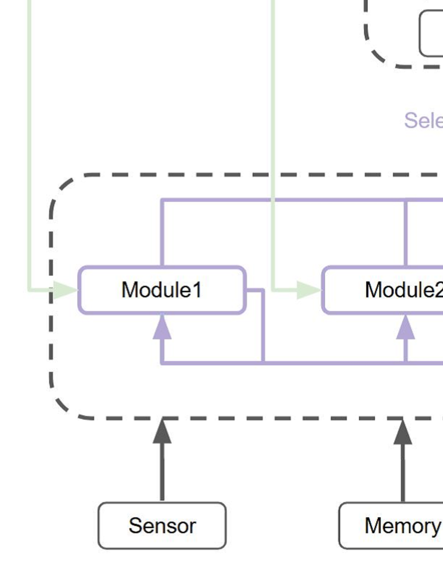
The diagram illustrates a system architecture with bidirectional data flow between two modules (Module1 and Module2), a sensor, and a memory component. A dashed rectangular boundary encloses the modules, while a green vertical line runs along the right edge. Arrows indicate directional relationships, with color-coded pathways (purple and green) suggesting distinct data flows.
### Components/Axes
- **Modules**:
- Module1 (left)
- Module2 (right)
- **Data Flow Elements**:
- Sensor (bottom-left)
- Memory (bottom-center)
- **Visual Boundaries**:
- Dashed rectangle (enclosing Module1 and Module2)
- Green vertical line (right edge)
### Detailed Analysis
1. **Module1**:
- Receives input from the Sensor (green arrow).
- Sends output to Module2 (purple arrow).
- Receives feedback from Memory (purple arrow).
2. **Module2**:
- Receives input from Module1 (purple arrow).
- Sends output to the Sensor (purple arrow).
- Receives feedback from Memory (purple arrow).
3. **Sensor**:
- Sends data to Module1 (green arrow).
- Receives data from Module2 (purple arrow).
4. **Memory**:
- Sends data to Module1 (purple arrow).
- Sends data to Module2 (purple arrow).
5. **Visual Elements**:
- Dashed rectangle: Likely demarcates a subsystem or processing boundary.
- Green vertical line: May represent a security boundary, communication channel, or system division.
### Key Observations
- **Bidirectional Flow**: Modules and Memory engage in reciprocal data exchange, suggesting real-time processing or iterative workflows.
- **Color-Coded Pathways**:
- Green arrows (Sensor ↔ Module1) may indicate primary input/output streams.
- Purple arrows (inter-module and Memory interactions) suggest secondary or control pathways.
- **Dashed Boundary**: Implies modularity or isolation of Module1 and Module2 from external components.
- **Green Vertical Line**: Positioned at the system’s right edge, possibly denoting a termination point or external interface.
### Interpretation
The diagram represents a closed-loop system where Module1 and Module2 process data from the Sensor and Memory, with feedback mechanisms ensuring continuous operation. The green vertical line might symbolize a critical boundary (e.g., security, resource allocation) separating the core modules from external systems. The bidirectional arrows between modules and Memory highlight a design prioritizing data redundancy or fault tolerance.
**Notable Patterns**:
- Module2 acts as an intermediary between Module1 and the Sensor, suggesting a hierarchical or sequential processing role.
- Memory serves as a shared resource for both modules, indicating centralized data storage or caching.
**Uncertainties**:
- The exact purpose of the green vertical line remains ambiguous without additional context.
- The dashed rectangle’s significance (e.g., security, abstraction) is inferred but not explicitly labeled.