## Diagram: State Transition Flowchart for a 4x4 Grid Puzzle
### Overview
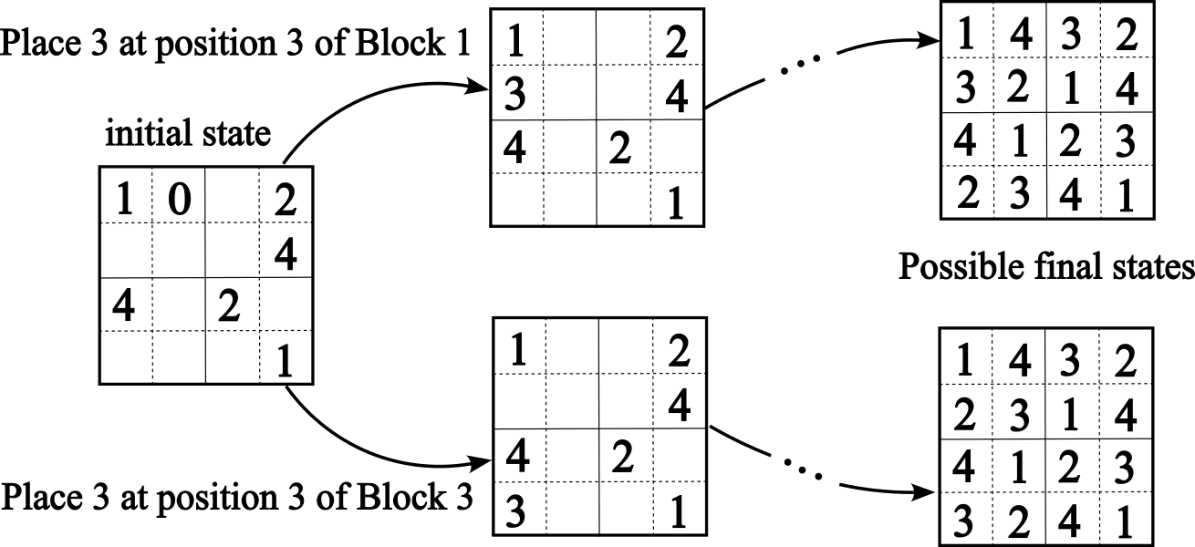
The image is a technical diagram illustrating a state transition process for a 4x4 grid-based puzzle or algorithm. It shows an "initial state" grid, two distinct branching operations ("Place 3 at position 3 of Block 1" and "Place 3 at position 3 of Block 3"), each leading to an intermediate grid state, and then to a set of "Possible final states." The diagram uses arrows to indicate the flow of operations and dotted lines within the grids to suggest sub-blocks (likely 2x2 blocks, common in puzzles like Sudoku).
### Components/Axes
* **Layout:** The diagram flows from left to right.
* **Left:** A single grid labeled "initial state".
* **Center:** Two parallel branches, each starting with a text instruction and leading to an intermediate grid.
* **Right:** Two final grids, each labeled collectively as "Possible final states".
* **Grid Structure:** Each grid is a 4x4 matrix. Dotted lines divide each grid into four 2x2 quadrants or "blocks."
* **Text Labels:**
* "initial state" (above the leftmost grid)
* "Place 3 at position 3 of Block 1" (above the top branch arrow)
* "Place 3 at position 3 of Block 3" (below the bottom branch arrow)
* "Possible final states" (below the two rightmost grids)
* **Arrows:** Solid black arrows show the direction of state transition. Ellipses ("...") on the arrows from intermediate to final states indicate additional, unstated steps.
### Detailed Analysis
**1. Initial State Grid (Leftmost)**
A 4x4 grid with the following numbers placed (row, column):
* Row 1: `1`, `0`, ` `, `2`
* Row 2: ` `, ` `, ` `, `4`
* Row 3: `4`, ` `, `2`, ` `
* Row 4: ` `, ` `, ` `, `1`
*(Note: Empty cells are represented by a space. The `0` is unusual and may represent a blank or a special value.)*
**2. Top Branch: "Place 3 at position 3 of Block 1"**
* **Instruction:** This operation targets "Block 1" (the top-left 2x2 quadrant) and places the number `3` at its "position 3." Assuming positions are numbered left-to-right, top-to-bottom within a block, position 3 would be the bottom-left cell of that block (Row 2, Column 1).
* **Intermediate Grid (Top Center):** The result of applying the instruction to the initial state.
* Row 1: `1`, ` `, ` `, `2`
* Row 2: `3`, ` `, ` `, `4`
* Row 3: `4`, ` `, `2`, ` `
* Row 4: ` `, ` `, ` `, `1`
* *Change from Initial:* The `0` in (R1,C2) is gone. A `3` appears in (R2,C1), consistent with the instruction.
* **Possible Final State (Top Right):** One possible grid after further unspecified steps.
* Row 1: `1`, `4`, `3`, `2`
* Row 2: `3`, `2`, `1`, `4`
* Row 3: `4`, `1`, `2`, `3`
* Row 4: `2`, `3`, `4`, `1`
* *Observation:* This is a complete, valid Latin square (each number 1-4 appears exactly once in each row and column).
**3. Bottom Branch: "Place 3 at position 3 of Block 3"**
* **Instruction:** This operation targets "Block 3" (the bottom-left 2x2 quadrant) and places the number `3` at its "position 3." This would be the bottom-left cell of that block (Row 4, Column 1).
* **Intermediate Grid (Bottom Center):** The result of applying this different instruction to the initial state.
* Row 1: `1`, ` `, ` `, `2`
* Row 2: ` `, ` `, ` `, `4`
* Row 3: `4`, ` `, `2`, ` `
* Row 4: `3`, ` `, ` `, `1`
* *Change from Initial:* The `0` in (R1,C2) is gone. A `3` appears in (R4,C1), consistent with the instruction.
* **Possible Final State (Bottom Right):** One possible grid after further unspecified steps.
* Row 1: `1`, `4`, `3`, `2`
* Row 2: `2`, `3`, `1`, `4`
* Row 3: `4`, `1`, `2`, `3`
* Row 4: `3`, `2`, `4`, `1`
* *Observation:* This is also a complete, valid Latin square, but it differs from the top final state in rows 2 and 4.
### Key Observations
1. **Branching Decision Point:** The core of the diagram is a single decision: where to place the number `3` in the initial state. This choice creates two distinct solution paths.
2. **Identical Starting Point:** Both branches begin from the exact same "initial state" grid.
3. **Divergent Intermediates:** The two instructions produce different intermediate grids, differing only in the location of the newly placed `3` and the removal of the `0`.
4. **Convergent Structure, Divergent Content:** Both paths lead to a fully solved grid (a Latin square). The final states share the same first and third rows (`1,4,3,2` and `4,1,2,3`) but have different second and fourth rows.
5. **Role of the "0":** The `0` in the initial state is removed in both intermediate states, suggesting it might be a placeholder or an error that is corrected by the placement of a `3`.
### Interpretation
This diagram is a **decision tree for a constraint satisfaction problem**, likely a variant of a 4x4 Sudoku or a Latin square puzzle with pre-filled clues. It demonstrates how a single, early choice (the placement of the number `3`) propagates through the system and fundamentally alters the final solution space.
* **What it demonstrates:** The puzzle has multiple valid solutions. The diagram explicitly maps two distinct solution pathways originating from one initial configuration. The "..." implies that the solver must make further logical deductions after placing the initial `3` to reach the final state.
* **Relationship between elements:** The "initial state" is the root. The "Place 3..." instructions are the first branching operations. The "intermediate states" are the direct results of those operations. The "Possible final states" are the end products of completing the puzzle along each branch.
* **Notable Anomalies/Patterns:** The presence of `0` in the initial state is atypical for such puzzles and is treated as a cell to be filled. The fact that both final states are valid Latin squares confirms the puzzle's consistency. The diagram's purpose is likely pedagogical or analytical, showing how backtracking or choice points work in puzzle-solving algorithms. It visually argues that the solution is not unique and depends critically on early decisions.