## Circuit Diagram: Four-Stage Neuromorphic Circuit
### Overview
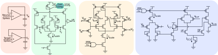
The image presents a circuit diagram composed of four distinct stages, each highlighted with a different background color (red, green, orange, and blue). These stages appear to represent a neuromorphic circuit, likely designed for spike-based processing. The diagram includes transistors, capacitors, operational amplifiers, and logic gates, interconnected to perform a specific function related to neuron and target spike processing.
### Components/Axes
* **Stage 1 (Red Background):**
* Two operational amplifiers (op-amps) are shown.
* The top op-amp has "Neuron Spikes" as input to the positive terminal and outputs a voltage labeled "VN".
* The bottom op-amp has "Target Spikes" as input to the positive terminal and outputs a voltage labeled "VT".
* Each op-amp output is connected to a capacitor, which is grounded.
* **Stage 2 (Green Background):**
* This stage contains a complex arrangement of transistors.
* Labels include: "ref", "Curr. Comp", "STOP", "Isubth", "VN", "VT", and "UP" (connected to an inverter).
* **Stage 3 (Orange Background):**
* This stage also contains a complex arrangement of transistors.
* Labels include: "VSF", "VerrP", "VerrN", "Iscale", "STOP", and "Pre".
* A NAND gate is labeled "STOP" and "Pre" as inputs.
* **Stage 4 (Blue Background):**
* This stage contains transistors and a NAND gate.
* Labels include: "STOP", "Pre", "Iscale", "Ve", "Ie_s", "VerrP", "VerrN", "UP", "UP", and "Icc1".
* A NAND gate is labeled "STOP" and "Pre" as inputs.
### Detailed Analysis
* **Stage 1 (Red):** The op-amps likely convert the input spike signals (Neuron Spikes and Target Spikes) into corresponding voltages VN and VT. The capacitors likely serve as integrators or filters.
* **Stage 2 (Green):** This stage appears to be a comparator or current mirror circuit. The "Curr. Comp" label suggests a current comparison function. "Isubth" likely refers to a subthreshold current. The "UP" signal is likely an output indicating the result of the comparison.
* **Stage 3 (Orange):** This stage seems to be related to error amplification and scaling. "VerrP" and "VerrN" likely represent positive and negative error voltages. "Iscale" likely represents a scaling current. The NAND gate with "STOP" and "Pre" inputs likely controls the operation of this stage.
* **Stage 4 (Blue):** This stage appears to be involved in generating a control signal based on the error voltages. "Ve" likely represents an error voltage. "Ie_s" likely represents an error current. "Icc1" likely represents a control current. The "UP" and "UP" signals likely control the direction of the correction.
### Key Observations
* The circuit is highly interconnected, with signals flowing between the different stages.
* The use of transistors and capacitors suggests analog signal processing.
* The presence of logic gates suggests digital control or decision-making.
* The labels "Neuron Spikes" and "Target Spikes" suggest that the circuit is designed for processing neural signals.
### Interpretation
The circuit diagram likely represents a neuromorphic system designed to compare neuron and target spike rates and generate a control signal to adjust the neuron's behavior. The first stage converts spike rates into voltages. The second stage compares these voltages. The third stage amplifies the error between the voltages. The fourth stage generates a control signal based on the amplified error. The "STOP" and "Pre" signals likely provide a mechanism to halt or reset the circuit's operation. The overall system appears to implement a form of spike-timing-dependent plasticity (STDP) or a similar learning rule.