## CircuitDiagrams: Neural Interface and Control System Components
### Overview
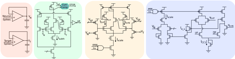
The image contains four distinct circuit diagrams, each illustrating components of a neural interface or adaptive control system. Diagrams are color-coded (pink, green, orange, blue) and feature operational amplifiers (op-amps), microcontrollers, resistors, capacitors, and labeled signal paths.
### Components/Axes
#### Diagram 1 (Pink)
- **Components**:
- Two op-amps labeled "Neuron Spikes" (input: `V_N`) and "Target Spikes" (input: `V_T`).
- Output connected to a comparator (symbol: `+ -` with output line).
- **Key Labels**:
- `V_N` (Neuron voltage), `V_T` (Target voltage).
#### Diagram 2 (Green)
- **Components**:
- Multiple op-amps, resistors (`R`), capacitors (`C`), and a microcontroller (`MCU`).
- Feedback loops with labeled nodes: `Curr. Comp.` (current comparator), `STOP`, `UP`.
- Voltage nodes: `V_SF`, `V_ErrP`, `V_ErrN`, `V_subth`.
- Current nodes: `I_scale`, `I_errP`, `I_errN`, `I_CC1`.
- **Key Labels**:
- `STOP` (control signal), `UP` (control signal), `V_SF` (scaled feedback voltage).
#### Diagram 3 (Orange)
- **Components**:
- Op-amps, resistors, capacitors, and a microcontroller.
- Error correction nodes: `V_ErrP`, `V_ErrN`, `I_errP`, `I_errN`.
- Scaling nodes: `I_scale`, `I_CC1`.
- **Key Labels**:
- `STOP` (control signal), `UP` (control signal), `V_SF` (scaled feedback voltage).
#### Diagram 4 (Blue)
- **Components**:
- Microcontroller (`MCU`), op-amps, resistors, capacitors.
- Scaling and error nodes: `I_scale`, `I_errP`, `I_errN`, `V_ErrP`, `V_ErrN`.
- Additional nodes: `V_e` (error voltage), `I_CC1` (current correction).
- **Key Labels**:
- `STOP` (control signal), `UP` (control signal), `V_SF` (scaled feedback voltage).
### Detailed Analysis
- **Diagram 1**: A comparator circuit comparing neuron and target spike voltages (`V_N` vs. `V_T`). Output polarity depends on which voltage is higher.
- **Diagram 2**: A feedback control system with error correction (`V_ErrP`, `V_ErrN`) and scaling (`I_scale`). The microcontroller (`MCU`) likely processes signals for adaptive adjustments.
- **Diagram 3**: Similar to Diagram 2 but emphasizes error current (`I_errP`, `I_errN`) and scaling (`I_scale`). The `STOP` and `UP` signals suggest conditional control logic.
- **Diagram 4**: Integrates error voltage (`V_e`) and current correction (`I_CC1`) with scaling (`I_scale`). The `MCU` appears central to coordinating feedback loops.
### Key Observations
1. **Repetition of Labels**: `STOP`, `UP`, `V_SF`, and `I_scale` appear across multiple diagrams, indicating standardized control signals.
2. **Error Handling**: All diagrams include error voltage (`V_ErrP`, `V_ErrN`) and current (`I_errP`, `I_errN`) nodes, suggesting a focus on precision and adaptability.
3. **Scaling Mechanisms**: `I_scale` and `V_SF` imply dynamic adjustment of signals, possibly for noise reduction or signal amplification.
### Interpretation
These diagrams likely represent a neural interface system where:
- **Neuron/Target Comparison** (Diagram 1) detects discrepancies between neural activity and desired outputs.
- **Feedback Control** (Diagrams 2–4) uses error signals to adjust system behavior via scaling and correction currents.
- **Microcontroller Integration** (`MCU`) enables real-time processing of feedback loops, allowing adaptive responses to neural inputs.
The system may be used in applications like brain-computer interfaces, where precise error correction and dynamic scaling are critical for accurate signal interpretation. The repeated use of `STOP` and `UP` signals suggests conditional logic for halting or adjusting operations based on error thresholds.