## Diagram: System Architecture for QUBO Workload Processing on Loihi 2
### Overview
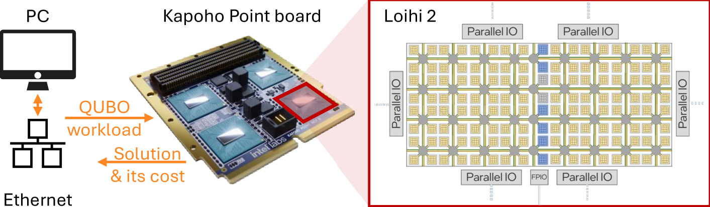
The image illustrates a hardware-in-the-loop system architecture where a host computer (PC) offloads a specific computational task—a "QUBO workload"—to an Intel "Kapoho Point board" equipped with Loihi 2 neuromorphic chips. The board processes the workload and returns a "Solution & its cost." The right side of the image provides a schematic representation of the internal architecture of the Loihi 2 chip, highlighting its grid-based core structure and I/O interfaces.
### Components/Axes
**1. Left Section (Host System):**
* **PC Icon:** Represents the host computer.
* **Ethernet Icon:** Represents the network connection (switch/hub symbol) between the PC and the hardware board.
* **Flow Arrows:**
* **Top Arrow:** Labeled "QUBO workload" (orange text), pointing from the PC/Ethernet system toward the Kapoho Point board.
* **Bottom Arrow:** Labeled "Solution & its cost" (orange text), pointing from the Kapoho Point board back toward the PC/Ethernet system.
**2. Center Section (Hardware):**
* **Kapoho Point board:** A physical circuit board featuring multiple integrated circuit chips.
* **Highlight:** One specific chip on the board is outlined with a red square, which visually connects to the Loihi 2 schematic on the right.
**3. Right Section (Schematic):**
* **Loihi 2:** A schematic diagram of the chip architecture, enclosed in a red border.
* **Grid Structure:** A matrix of small squares representing neuromorphic processing cores.
* **Parallel IO:** Four blocks labeled "Parallel IO" located at the top, bottom, left, and right edges of the chip schematic.
* **FPIO:** A block labeled "FPIO" (Flexible Pin IO) located at the bottom center of the schematic.
* **Highlight:** A vertical column of cores in the right-center of the grid is highlighted in blue.
### Detailed Analysis
* **Workflow:** The system operates as a request-response loop. The PC transmits a Quadratic Unconstrained Binary Optimization (QUBO) problem to the Kapoho Point board. The board, utilizing the Loihi 2 architecture, computes the optimization and returns the resulting solution along with the associated cost (the value of the objective function).
* **Hardware Architecture (Loihi 2):**
* The schematic depicts a highly parallel, tiled architecture.
* The "Parallel IO" blocks suggest high-bandwidth connectivity for data ingestion and extraction.
* The "FPIO" (Flexible Pin IO) indicates configurable input/output pins, likely used for interfacing with external sensors or other hardware components.
* The blue-highlighted column of cores suggests that the QUBO workload may be mapped to a specific subset of the chip's neuromorphic fabric, or that this region is currently active/being monitored.
### Key Observations
* **QUBO Focus:** The explicit mention of "QUBO" (Quadratic Unconstrained Binary Optimization) indicates that this specific hardware setup is being utilized for combinatorial optimization tasks, which is a non-traditional use case for neuromorphic chips (typically used for spiking neural networks).
* **Spatial Mapping:** The red highlight on the physical Kapoho Point board directly corresponds to the red-bordered Loihi 2 schematic, confirming that the schematic represents the internal logic of the chips mounted on the board.
* **Closed-Loop Optimization:** The return of "cost" alongside the "solution" is critical; it implies the system is performing iterative optimization where the chip minimizes an energy function to find the best solution.
### Interpretation
This diagram demonstrates the repurposing of Intel's neuromorphic Loihi 2 hardware for solving optimization problems.
* **Why it matters:** Traditional CPUs often struggle with the massive parallelism required for certain combinatorial optimization problems. By mapping QUBO problems onto the Loihi 2's neuromorphic fabric, the system can potentially achieve significant speedups or energy efficiency gains.
* **Reading between the lines:** The blue column in the Loihi 2 schematic is likely not arbitrary; it represents a specific mapping of the QUBO problem onto the chip's grid. The "FPIO" and "Parallel IO" labels suggest that the chip is designed to be integrated into larger systems where real-time data throughput is required, rather than just being a standalone processor. The "cost" return is the most significant indicator of the chip's function here: it is acting as an energy-minimization engine, where the "cost" corresponds to the energy state of the neural network representing the QUBO problem.