## System Diagram: Kapoho Point Board and Loihi 2 Architecture
### Overview
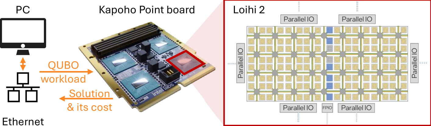
The image presents a system diagram illustrating the connection between a PC, a Kapoho Point board, and the architecture of a Loihi 2 chip. The diagram highlights the flow of QUBO workloads and solutions between the PC and the Kapoho Point board, and provides a detailed view of the Loihi 2 chip's parallel processing architecture.
### Components/Axes
* **PC:** Represents a personal computer.
* **Ethernet:** Indicates the network connection between the PC and other components.
* **Kapoho Point board:** A circuit board with multiple chips.
* **Loihi 2:** A neuromorphic computing chip.
* **QUBO workload:** Represents the workload sent from the PC to the Kapoho Point board.
* **Solution & its cost:** Represents the solution and associated cost returned from the Kapoho Point board to the PC.
* **Parallel IO:** Indicates parallel input/output connections in the Loihi 2 architecture.
* **FPIO:** Indicates a specific type of parallel input/output connection in the Loihi 2 architecture.
### Detailed Analysis
* **PC and Ethernet:** A standard PC is connected via Ethernet.
* **QUBO Workload Flow:** The PC sends a "QUBO workload" to the Kapoho Point board.
* **Solution Flow:** The Kapoho Point board returns a "Solution & its cost" to the PC.
* **Kapoho Point Board:** The board has multiple chips, one of which is highlighted with a red box. The text "intel labs" is visible on the board.
* **Loihi 2 Architecture:** The Loihi 2 chip is depicted as a grid of interconnected processing units.
* The grid consists of multiple small squares, most of which are yellow with a grid pattern inside.
* Some squares are blue.
* The squares are interconnected by grey lines, with grey circles at the intersections.
* "Parallel IO" labels are placed around the perimeter of the grid.
* "FPIO" is labeled at the bottom center of the grid.
### Key Observations
* The diagram illustrates a system where a PC offloads computational tasks (QUBO workloads) to specialized hardware (Kapoho Point board with Loihi 2 chip).
* The Loihi 2 architecture emphasizes parallel processing through its grid-like structure and numerous parallel I/O connections.
### Interpretation
The diagram showcases a system designed for efficient QUBO (Quadratic Unconstrained Binary Optimization) problem-solving. The PC acts as the host, sending workloads to the Kapoho Point board, which likely contains the Loihi 2 chip optimized for such computations. The Loihi 2 architecture, with its parallel processing capabilities, suggests a design aimed at accelerating the solution of complex optimization problems. The "Solution & its cost" feedback loop indicates that the system not only provides solutions but also quantifies the computational resources or energy expended in finding them.