\n
## Diagram: System Architecture - QUBO Workload Solution
### Overview
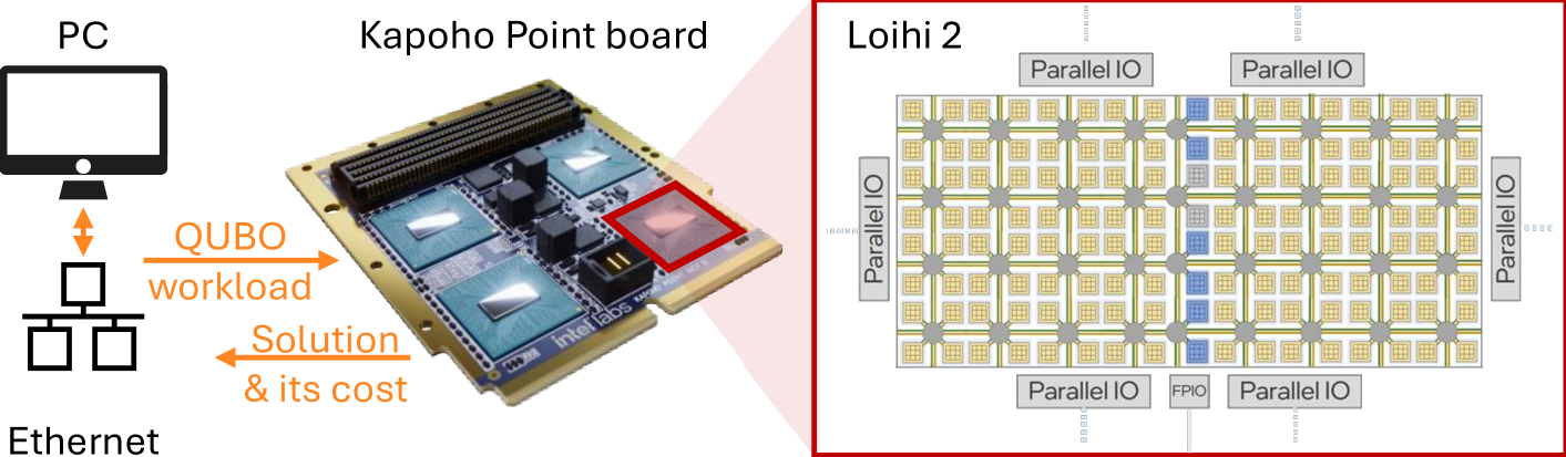
This diagram illustrates the system architecture for solving QUBO (Quadratic Unconstrained Binary Optimization) workloads, utilizing a Kapoho Point board and a Loihi 2 neuromorphic processor. The diagram depicts the flow of data from a PC through Ethernet, to the Kapoho Point board, and finally to the Loihi 2 chip. It also highlights the output of the solution and its associated cost.
### Components/Axes
The diagram consists of four main components:
1. **PC:** Represented by a computer monitor icon.
2. **Kapoho Point board:** A photograph of a circuit board with visible components.
3. **Loihi 2:** A grid-like representation of the neuromorphic processor.
4. **Ethernet:** Represented by a network cable icon.
Additionally, there are labeled arrows indicating data flow:
* "QUBO workload" - Orange arrow from PC to Kapoho Point board.
* "Solution & cost" - Orange arrow from Kapoho Point board to PC.
* "Parallel IO" - Labels surrounding the Loihi 2 grid.
* "FPIO" - Label within the Loihi 2 grid.
### Detailed Analysis or Content Details
* **PC:** Located in the top-left corner. Represents the computational source for the QUBO workload.
* **Ethernet:** Located in the bottom-left corner. Represents the network connection between the PC and the Kapoho Point board.
* **Kapoho Point board:** Positioned in the center of the diagram. It appears to be a blue circuit board with several gold-colored components. The label "intel labs" is visible on the board.
* **Loihi 2:** Located in the top-right corner. It is represented as a 20x15 grid of square cells. Each cell is labeled "Parallel IO" along the edges. A smaller section within the grid is labeled "FPIO". The grid is interconnected by thin white lines.
* **Data Flow:** The orange arrows indicate a two-way communication. The QUBO workload is sent from the PC to the Kapoho Point board, which then processes it using the Loihi 2 chip and returns the solution and its associated cost back to the PC.
### Key Observations
The diagram emphasizes the integration of conventional computing (PC) with neuromorphic computing (Loihi 2) via the Kapoho Point board. The Loihi 2 chip's grid structure suggests a massively parallel processing architecture. The "Parallel IO" labels indicate that the chip is designed for high-bandwidth input/output operations. The presence of "FPIO" suggests a specific type of input/output functionality.
### Interpretation
This diagram illustrates a hybrid computing approach to solving QUBO problems. The PC likely formulates the QUBO problem, while the Loihi 2 chip, facilitated by the Kapoho Point board, leverages its neuromorphic architecture to efficiently find solutions. The return of "Solution & cost" suggests that the system not only provides an answer but also quantifies the computational resources used. The diagram highlights the potential of neuromorphic computing to accelerate optimization tasks. The architecture suggests a specialized hardware accelerator for QUBO problems, rather than a general-purpose computing solution. The diagram does not provide specific performance metrics or cost details, but it conceptually outlines the system's functionality.