\n
## Diagram: Logic Puzzle Grid
### Overview
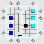
The image depicts a logic puzzle grid, likely a type of flow puzzle or maze. The grid is a square, bordered by a red rectangle. There are input points on the left side, output points on the right side, and internal components that appear to direct flow. The puzzle appears to involve connecting the input points to the output points using the available pathways.
### Components/Axes
The diagram consists of:
* **Grid:** A square grid composed of smaller square cells.
* **Input Points:** Three blue square components located on the left side of the grid.
* **Output Points:** Three cyan (light blue) square components located on the right side of the grid.
* **Flow Controller:** A black square component located in the center of the grid.
* **Pathways:** Black lines connecting the input, output, and flow controller components.
* **Arrows:** Grey arrows pointing inwards towards the grid, positioned around the perimeter.
### Detailed Analysis or Content Details
The grid is approximately 7x7 cells. The input points are vertically aligned on the left side. The output points are vertically aligned on the right side. The flow controller is positioned roughly in the center of the grid.
* **Input 1 (Top):** Connected to the flow controller via a vertical pathway.
* **Input 2 (Middle):** Connected to the flow controller via a vertical pathway.
* **Input 3 (Bottom):** Connected to the flow controller via a vertical pathway.
* **Flow Controller:** Connected to the top and middle output points via pathways. The bottom output point is not directly connected to the flow controller.
* **Output 1 (Top):** Connected to the flow controller.
* **Output 2 (Middle):** Connected to the flow controller.
* **Output 3 (Bottom):** Not directly connected to the flow controller.
The arrows around the perimeter suggest inputs or constraints to the puzzle.
### Key Observations
The puzzle appears to require routing the inputs to the outputs using the available pathways and the flow controller. The bottom output point is isolated, suggesting a unique solution path or constraint. The flow controller acts as a central hub for directing the flow.
### Interpretation
This diagram represents a logic puzzle where the goal is to establish a valid flow from the input points to the output points, adhering to the constraints imposed by the grid layout and the flow controller. The puzzle likely requires deductive reasoning to determine the correct pathway configuration. The isolated bottom output point suggests a more complex routing requirement. The arrows around the perimeter could represent additional constraints or input conditions that must be satisfied. The puzzle is likely designed to test spatial reasoning and problem-solving skills. The diagram does not contain any numerical data or quantitative information; it is purely a visual representation of a logical problem.