\n
## Diagram: Neuro-Symbolic AI Architecture and Applications
### Overview
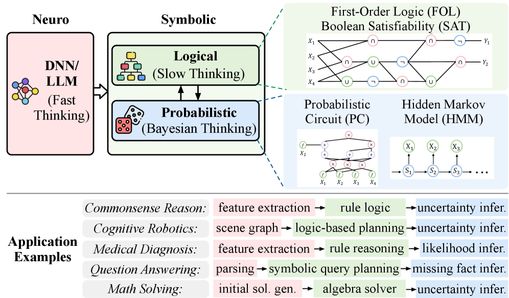
This image is a technical diagram illustrating a hybrid neuro-symbolic artificial intelligence architecture. It visually explains how neural networks (fast thinking) integrate with symbolic reasoning systems (slow, logical, and probabilistic thinking) and provides concrete application examples of this combined approach.
### Components/Axes
The diagram is organized into three main horizontal sections:
1. **Top Section (Architecture Diagram):**
* **Left Block (Pink):** Labeled "Neuro". Contains an icon of a neural network and the text "DNN/LLM (Fast Thinking)".
* **Center Block (Green/Blue):** Labeled "Symbolic". This is a larger container split into two sub-blocks:
* **Top Sub-block (Green):** Labeled "Logical (Slow Thinking)" with a logic gate icon.
* **Bottom Sub-block (Blue):** Labeled "Probabilistic (Bayesian Thinking)" with a dice icon.
* **Right Section (Detailed Models):** This area expands on the "Symbolic" components with two shaded boxes:
* **Top Box (Light Green):** Titled "First-Order Logic (FOL) Boolean Satisfiability (SAT)". Contains a circuit-like diagram with inputs `X₁`, `X₂`, `X₃`, `X₄` connected through logical operators (∩, ∪, ¬) to outputs `Y₁`, `Y₂`.
* **Bottom Box (Light Blue):** Contains two models:
* **Left Model:** Titled "Probabilistic Circuit (PC)". Shows a network diagram with inputs `X₁`, `X₂`, `X₃`, `X₄` connected to nodes labeled `f` and `g` with multiplication (×) and addition (+) operations.
* **Right Model:** Titled "Hidden Markov Model (HMM)". Shows a state transition diagram with observed states `X₁`, `X₂`, `X₃` and hidden states `S₁`, `S₂`, `S₃` connected in a chain.
2. **Bottom Section (Application Examples):**
* **Left Column:** Header "Application Examples".
* **Main Grid:** A 5-row table mapping application domains to a three-stage pipeline. Each row has a domain name followed by three process steps connected by arrows (→). The steps are color-coded to correspond with the architecture above (pink for neural, green for logical, blue for probabilistic).
| Application Domain | Stage 1 (Neural - Pink) | Stage 2 (Logical - Green) | Stage 3 (Probabilistic - Blue) |
|--------------------|-------------------------|---------------------------|--------------------------------|
| Commonsense Reason | feature extraction → | rule logic → | uncertainty infer. |
| Cognitive Robotics | scene graph → | logic-based planning → | uncertainty infer. |
| Medical Diagnosis | feature extraction → | rule reasoning → | likelihood infer. |
| Question Answering | parsing → | symbolic query planning → | missing fact infer. |
| Math Solving | initial sol. gen. → | algebra solver → | uncertainty infer. |
### Detailed Analysis
**Architecture Flow:**
The diagram shows a directional flow from left to right. The "Neuro" (DNN/LLM) component, responsible for "Fast Thinking," feeds into the "Symbolic" component. The Symbolic component is bifurcated into "Logical (Slow Thinking)" and "Probabilistic (Bayesian Thinking)" modules, which interact bidirectionally (indicated by up/down arrows between them). Dashed lines connect these high-level symbolic modules to their specific formal implementations (FOL/SAT, PC, HMM) on the right.
**Application Pipeline Details:**
Each application follows a consistent three-stage pattern:
1. **Stage 1 (Pink - Neural):** Initial data processing or representation.
2. **Stage 2 (Green - Logical):** Structured reasoning or planning.
3. **Stage 3 (Blue - Probabilistic):** Inference under uncertainty.
The specific pipelines are as shown in the table above.
### Key Observations
1. **Clear Conceptual Mapping:** The color coding (pink, green, blue) is consistently applied across the high-level architecture and the application pipelines, creating a strong visual link between theory and practice.
2. **Bidirectional Interaction:** The arrows between the "Logical" and "Probabilistic" blocks indicate that these reasoning modes are not sequential but interactive and mutually informative within the symbolic system.
3. **Formal Grounding:** The diagram explicitly connects abstract concepts ("Logical Thinking") to concrete, established formal methods (First-Order Logic, SAT), providing technical specificity.
4. **Pipeline Consistency:** All five diverse applications (from robotics to math) are shown to follow the same fundamental neuro-symbolic processing paradigm, suggesting the framework's generality.
### Interpretation
This diagram argues for a unified AI architecture that marries the pattern recognition strengths of neural networks ("fast thinking") with the rigorous, explainable reasoning of symbolic systems ("slow thinking"). The "Neuro" component likely handles raw data perception and initial feature extraction, while the "Symbolic" component performs structured reasoning, planning, and inference.
The inclusion of both deterministic (Logical/FOL) and stochastic (Probabilistic/Bayesian) models within the symbolic half acknowledges that real-world reasoning requires handling both strict rules and inherent uncertainty. The application examples demonstrate the practical value of this hybrid approach: it enables systems that can not only perceive and parse the world (via neural nets) but also plan, explain decisions, and reason about missing or uncertain information (via symbolic logic and probability).
The overall message is that moving beyond pure neural or pure symbolic AI towards an integrated neuro-symbolic paradigm is a powerful direction for creating more robust, generalizable, and trustworthy AI systems capable of complex tasks like medical diagnosis and cognitive robotics.