## Diagram: Robotic Arm Structure and Block Interaction
### Overview
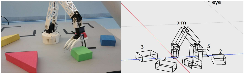
The image consists of two sections:
1. **Left**: A photograph of a robotic arm interacting with colored blocks (red, green, blue, yellow) on a gray surface.
2. **Right**: A technical diagram of the robotic arm's structure, labeled with numbered components and a legend mapping colors to parts.
---
### Components/Axes
#### Left Section (Photograph):
- **Robotic Arm**: White with black and red mechanical components.
- **Blocks**:
- Red triangle (bottom-left).
- Green cube (center).
- Blue cube (top-right).
- Yellow triangle (top-left).
#### Right Section (Diagram):
- **Labeled Components**:
- **1**: Base of the arm (black).
- **2**: Upper arm segment (black).
- **3**: Lower arm segment (black).
- **4**: Gripper (black).
- **5**: Block interaction point (black).
- **Legend**:
- Colors: Red, Green, Blue, Yellow, Black.
- Spatial grounding: Colors correspond to blocks in the photograph (e.g., red = red triangle, green = green cube).
---
### Detailed Analysis
#### Left Section:
- The robotic arm is positioned to interact with the green cube (labeled "3" in the diagram).
- Blocks are arranged in a grid-like pattern on the surface.
#### Right Section:
- **Structure**:
- The arm is composed of interconnected segments (1–4) and a gripper (4).
- Block interaction point (5) is near the gripper.
- **Legend**:
- Colors map to blocks in the photograph (e.g., red = red triangle, green = green cube).
---
### Key Observations
1. The robotic arm’s design (diagram) aligns spatially with the blocks in the photograph.
2. The legend’s colors (red, green, blue, yellow, black) correspond to the blocks and arm components.
3. The arm’s gripper (4) is positioned near the green cube (3) in the photograph.
---
### Interpretation
- The diagram provides a technical breakdown of the robotic arm’s structure, with numbered components and a color-coded legend for clarity.
- The photograph demonstrates the arm’s real-world interaction with blocks, validating the diagram’s spatial relationships.
- The legend’s color coding ensures unambiguous identification of blocks and arm parts, critical for programming or troubleshooting.
- No numerical data or trends are present; the focus is on structural and spatial relationships.