\n
## Diagram: Robotic Arm and Workspace
### Overview
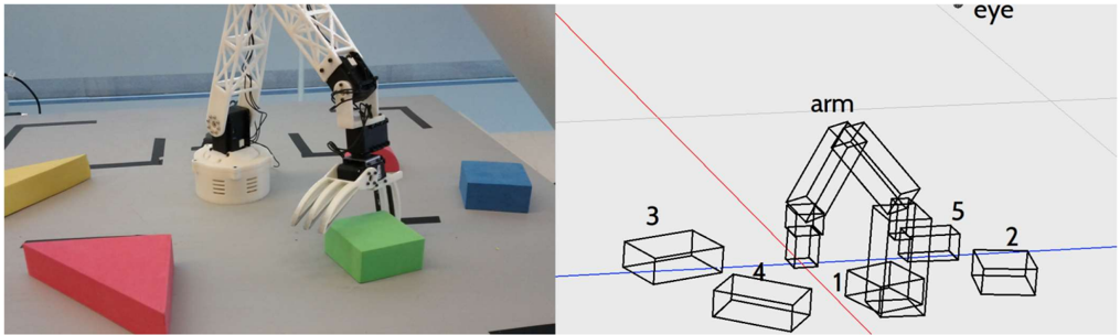
The image presents a split view. The left side shows a photograph of a robotic arm interacting with colored geometric shapes on a gridded surface. The right side is a simplified, wireframe diagram of the robotic arm and its surrounding workspace, with numbered blocks. The diagram appears to illustrate the arm's reach and potential interaction points.
### Components/Axes
The diagram includes the following labeled components:
* **eye**: Located in the top-right corner, indicating the arm's "viewpoint".
* **arm**: Labeling the robotic arm itself.
* Blocks numbered 1 through 5: Representing objects within the arm's workspace.
* A blue horizontal line: Likely representing a reference plane or the floor.
* A red diagonal line: Possibly indicating a constraint or path.
* The photograph shows a gridded surface with a yellow parallelepiped, a red triangle, a green cube, and a blue cube.
### Detailed Analysis or Content Details
The diagram shows a robotic arm positioned near several rectangular blocks. The blocks are numbered 1 through 5, and their positions relative to the arm are indicated.
* **Block 1**: Directly beneath the arm's "hand" or end effector.
* **Block 2**: To the right and slightly forward of the arm.
* **Block 3**: Further to the right and slightly behind the arm.
* **Block 4**: Directly below Block 3.
* **Block 5**: Directly above Block 1, partially obscured by the arm.
The photograph shows the robotic arm grasping a green cube. The arm is white and has multiple joints. The base of the arm is a circular structure with vertical ridges. The workspace is a gray gridded surface. The geometric shapes are:
* Yellow parallelepiped
* Red triangle
* Green cube (being grasped)
* Blue cube
The photograph shows the arm is positioned over the green cube, and the gripper is closed around it. The arm is extended, with several joints bent to reach the cube.
### Key Observations
The diagram simplifies the real-world scene shown in the photograph. The numbered blocks in the diagram correspond to the shapes in the photograph, but the diagram does not show the shapes' colors. The diagram emphasizes the arm's reach and the spatial relationships between the arm and the objects in its workspace. The red line in the diagram is a notable element, but its purpose is unclear without additional context.
### Interpretation
The image likely illustrates a robotic manipulation task. The photograph shows the arm successfully grasping an object, while the diagram provides a simplified representation of the workspace and potential interaction points. The diagram could be used for planning the arm's movements or for simulating different scenarios. The numbered blocks suggest a sequence of operations or a set of possible targets for the arm. The red line might represent a constraint on the arm's movement or a desired path. The "eye" label suggests the arm may have a vision system that is used to identify and locate objects in its workspace. The overall purpose of the image is to demonstrate the capabilities of the robotic arm and its ability to interact with objects in a structured environment. The diagram is a conceptual representation, while the photograph provides a real-world example.