## Diagram: Layered Node Network Structure
### Overview
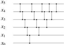
The image depicts a hierarchical, grid-like network diagram with six horizontal layers labeled **x₀** to **x₅** (from bottom to top). Each layer contains nodes connected by vertical and horizontal lines, forming a structured pattern. The diagram emphasizes connectivity between nodes across adjacent layers and within the same layer.
### Components/Axes
- **Horizontal Layers**:
- **x₀** (bottom layer): 1 node.
- **x₁**: 2 nodes.
- **x₂**: 3 nodes.
- **x₃**: 4 nodes.
- **x₄**: 5 nodes.
- **x₅** (top layer): 6 nodes.
- **Connections**:
- Vertical lines connect nodes between consecutive layers (e.g., x₀ → x₁, x₁ → x₂).
- Horizontal lines connect nodes within the same layer (e.g., x₁ nodes connected left-right).
- **Node Placement**:
- Nodes are evenly spaced along each layer.
- Vertical connections align nodes directly above/below.
- Horizontal connections span adjacent nodes within a layer.
### Detailed Analysis
- **Layer Progression**:
- Each layer **xₙ** contains **n+1** nodes (e.g., x₀: 1 node, x₅: 6 nodes).
- Nodes are labeled implicitly by position; no explicit node identifiers are provided.
- **Connection Patterns**:
- Vertical connections form a "staircase" pattern, linking each node to the node directly above it in the next layer.
- Horizontal connections create a grid, with each node (except the rightmost in a layer) connected to its immediate neighbor.
- **Symmetry**:
- The diagram is symmetric in structure but not in node count, as layers increase in node density upward.
### Key Observations
1. **Hierarchical Growth**: Node count increases linearly with layer index (x₀: 1, x₁: 2, ..., x₅: 6).
2. **Regular Connectivity**: All nodes (except boundary nodes) have **two connections**: one vertical (upward) and one horizontal (rightward).
3. **Boundary Nodes**:
- Leftmost nodes in each layer (e.g., x₁ left node) only connect vertically upward.
- Rightmost nodes (e.g., x₅ rightmost node) only connect vertically downward.
### Interpretation
This diagram likely represents a **multi-stage process** or **data flow system** where:
- **Layers (x₀–x₅)** correspond to sequential stages, with increasing complexity or capacity at higher layers.
- **Nodes** represent discrete units (e.g., tasks, data points, or entities) within each stage.
- **Connections** indicate dependencies or transitions:
- Vertical links suggest progression from one stage to the next.
- Horizontal links imply parallel processing or interdependencies within a stage.
The structured growth and connectivity imply a **scalable system** designed for incremental expansion, where each layer builds upon the previous one while maintaining internal cohesion. The absence of explicit labels for nodes suggests a generic model applicable to various domains (e.g., computational graphs, organizational hierarchies, or workflow pipelines).