## Neural Network Architecture Diagram: Component Flow and Operations
### Overview
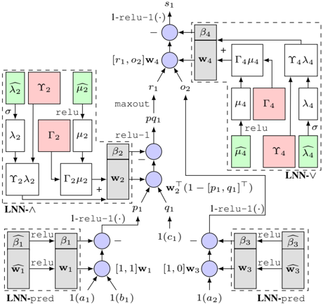
The diagram illustrates a multi-stage neural network architecture with three primary components: **LNN-A** (left), **LNN-V** (center), and **LNN-pred** (right). Each component contains interconnected operations (e.g., `relu`, `maxout`, parameterized layers) and data flow paths. The diagram uses color-coded blocks (pink, green, gray) to denote specific operations or layers, with arrows indicating data propagation.
---
### Components/Axes
#### Key Labels and Operations:
1. **LNN-A (Left Block)**:
- **Inputs**: `σ`, `λ₂`, `γ₂`, `μ₂`.
- **Operations**:
- `relu` (green block).
- `maxout` (pink block).
- Parameterized layers: `Γ₂μ₂`, `Γ₂λ₂`.
- **Outputs**: `w₂`, `pq₁`.
2. **LNN-V (Center Block)**:
- **Inputs**: `w₂`, `pq₁`.
- **Operations**:
- `1-relu(-1)` (gray block).
- `Γ₄μ₄`, `Γ₄λ₄` (parameterized layers).
- `maxout` (pink block).
- **Outputs**: `w₄`, `s₁`.
3. **LNN-pred (Right Block)**:
- **Inputs**: `w₁`, `w₃`, `1(a₁)`, `1(a₂)`, `1(c₁)`, `1(c₂)`.
- **Operations**:
- `β₁`, `β₂`, `β₃`, `β₄` (parameterized layers).
- `1-relu(-1)` (gray block).
- `relu` (green block).
- **Outputs**: `1(a₁)`, `1(a₂)`, `1(c₁)`, `1(c₂)`.
#### Arrows and Data Flow:
- **Top Path**: `s₁` → `Γ₄μ₄` → `Γ₄λ₄` → `LNN-V`.
- **Middle Path**: `w₂` → `1-relu(-1)` → `Γ₂μ₂` → `Γ₂λ₂` → `LNN-A`.
- **Bottom Path**: `w₁`, `w₃` → `β₁`, `β₂`, `β₃`, `β₄` → `LNN-pred`.
#### Color Legend:
- **Pink**: `maxout` operations.
- **Green**: `relu` operations.
- **Gray**: `1-relu(-1)` operations.
---
### Detailed Analysis
#### LNN-A (Left Block):
- **Flow**:
1. Inputs `σ`, `λ₂`, `γ₂`, `μ₂` are processed through `relu` (green).
2. Outputs are combined via `maxout` (pink) to produce `w₂` and `pq₁`.
- **Parameters**:
- `Γ₂μ₂`, `Γ₂λ₂` suggest matrix multiplications or transformations.
#### LNN-V (Center Block):
- **Flow**:
1. `w₂` and `pq₁` are input to `1-relu(-1)` (gray), producing `r₁`, `o₂`.
2. `r₁` and `o₂` are combined with `w₄` via `maxout` (pink) to generate `s₁`.
- **Parameters**:
- `Γ₄μ₄`, `Γ₄λ₄` indicate further transformations.
#### LNN-pred (Right Block):
- **Flow**:
1. Inputs `w₁`, `w₃` are processed through `β₁`, `β₂`, `β₃`, `β₄` (parameterized layers).
2. Outputs are combined via `1-relu(-1)` (gray) and `relu` (green) to produce `1(a₁)`, `1(a₂)`, `1(c₁)`, `1(c₂)`.
- **Parameters**:
- `β₁`, `β₂`, `β₃`, `β₄` likely represent weights or biases.
---
### Key Observations
1. **Modular Design**: The architecture is divided into distinct modules (LNN-A, LNN-V, LNN-pred), each handling specific transformations.
2. **Non-Linear Activations**: `relu` and `maxout` operations introduce non-linearity, critical for learning complex patterns.
3. **Parameterized Layers**: Use of `Γ`, `β`, `λ`, and `μ` suggests trainable parameters optimized during training.
4. **Data Fusion**: Multiple input paths (e.g., `w₁`, `w₃`, `1(a₁)`) converge in LNN-pred, indicating feature integration.
---
### Interpretation
This diagram represents a **hybrid neural network** combining feedforward and recurrent-like structures. The use of `maxout` and `1-relu(-1)` suggests a focus on robustness to input variations. The parameterized layers (`Γ`, `β`) imply the model is trained end-to-end, with weights adjusted to minimize prediction error. The separation into LNN-A, LNN-V, and LNN-pred may reflect a **multi-task learning** setup, where each module addresses a specific subtask (e.g., feature extraction, validation, prediction). The absence of explicit numerical values indicates this is a **conceptual architecture** rather than a trained model with specific weights.