## Flowchart Diagram: System Interaction Model
### Overview
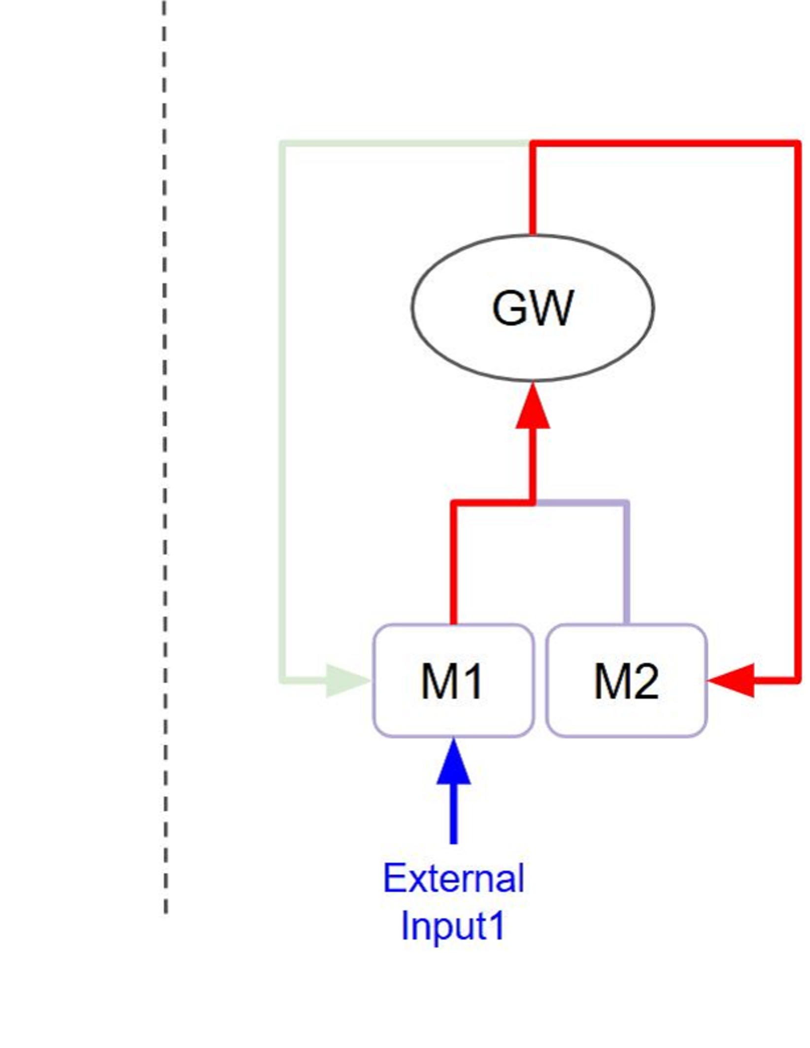
The diagram illustrates a feedback loop system with four primary components: GW (central oval), M1 and M2 (rectangular modules), and External Input1. Arrows indicate directional relationships between components, with color-coded connections and a green dashed boundary line.
### Components/Axes
- **Central Node**: GW (oval shape, black text)
- **Modules**:
- M1 (rectangle, purple border)
- M2 (rectangle, purple border)
- **External Input**: Input1 (blue arrow)
- **Connections**:
- Red arrow: GW → M1
- Blue arrow: M1 → External Input1
- Purple arrow: M1 → M2
- Red arrow: M2 → GW
- **Boundary**: Green dashed line from M2 to left edge
- **Legend**: Left-side dashed line patterns (green, red, blue, purple) with no labels
### Detailed Analysis
1. **GW Module**:
- Positioned centrally at the top
- Receives input from M2 (red arrow)
- Distributes output to M1 (red arrow)
2. **M1 Module**:
- Receives input from GW (red arrow)
- Sends output to External Input1 (blue arrow)
- Connects to M2 (purple arrow)
3. **M2 Module**:
- Receives input from M1 (purple arrow)
- Sends output back to GW (red arrow)
- Connected to external boundary via green dashed line
4. **External Input1**:
- Blue arrow originates from M1
- No return path shown
### Key Observations
- **Feedback Loop**: GW → M1 → M2 → GW creates a closed-loop system
- **External Interaction**: M1 interacts with External Input1 (unidirectional)
- **Boundary Element**: Green dashed line suggests system boundary or external interface
- **Color Consistency**: Red arrows dominate feedback paths; purple connects modules; blue handles external input
### Interpretation
This diagram represents a closed-loop control system with:
1. **Central Governance**: GW acts as the primary controller, receiving feedback from M2 and directing operations to M1
2. **Modular Processing**: M1 and M2 function as processing units with bidirectional communication
3. **External Interface**: M1 serves as the interface for External Input1, suggesting input validation or data preprocessing
4. **System Boundary**: The green dashed line implies a defined operational perimeter, possibly indicating security or resource constraints
The absence of legend labels for dashed lines suggests either:
- Intentional omission for simplicity
- Representation of non-critical system boundaries
- Placeholder for future annotations
The system appears designed for continuous operation with real-time feedback, where External Input1 may represent environmental data or user input requiring processing through M1 before system integration.