## Diagram: Architecture of an Approximate Processing Tensor Processing Unit (APTPU)
### Overview
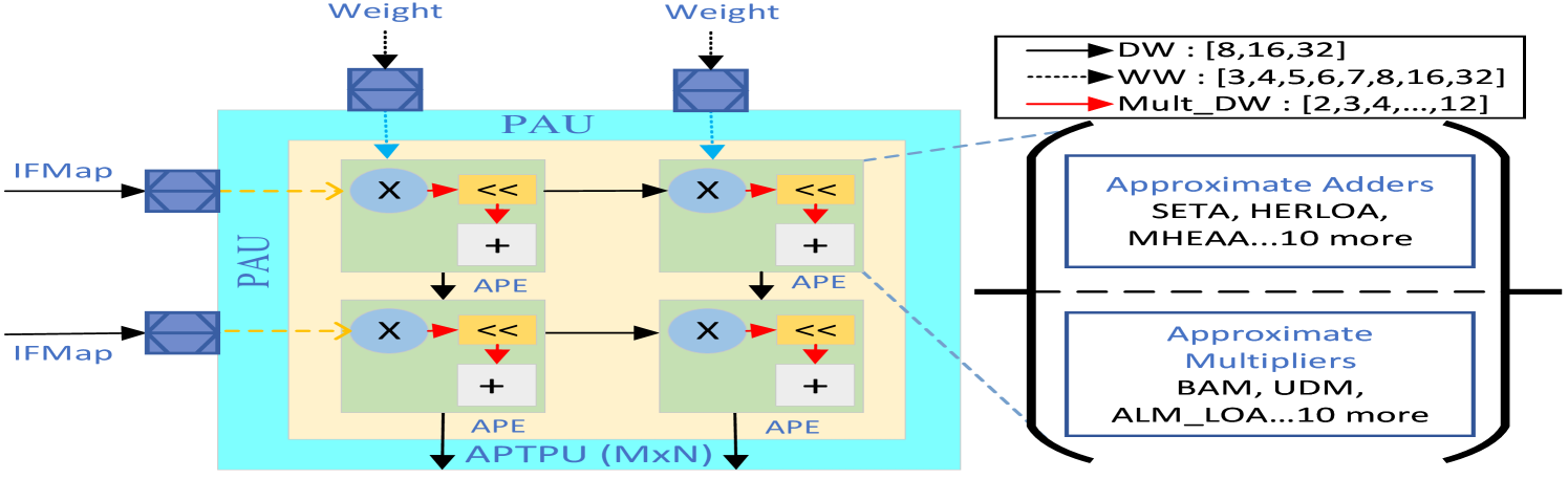
The image is a technical block diagram illustrating the architecture of an **APTPU (Approximate Processing Tensor Processing Unit)** of size **MxN**. The diagram depicts the data flow of **IFMap** (Input Feature Map) and **Weight** inputs into a grid of processing units. It also includes a legend defining parameter ranges for data widths and a list of specific approximate arithmetic components (adders and multipliers) utilized in the design.
### Components/Axes
**1. Main Diagram (Center-Left)**
* **Outer Boundary:** A large light-blue box labeled **PAU** (Processing Approximate Unit).
* **Processing Grid:** Inside the PAU, there is a 2x2 grid of green square processing units.
* **Internal Unit Logic:** Each green square contains:
* A circle labeled **X** (Multiplier).
* A yellow rectangle labeled **<<** (Shifter).
* A grey rectangle labeled **+** (Adder).
* A label **APE** located below the adder.
* **Inputs:**
* **IFMap:** Two inputs entering from the left, passing through blue square buffer/register blocks.
* **Weight:** Two inputs entering from the top, passing through blue square buffer/register blocks.
* **Flow:**
* Dashed yellow arrows indicate the flow of IFMap data into the processing units.
* Dashed blue arrows indicate the flow of Weight data into the processing units.
* Solid red arrows indicate internal data flow between the Multiplier (X) and the Shifter (<<).
* Solid black arrows indicate data flow between the Shifter (<<) and the Adder (+), as well as between processing units.
**2. Legend (Top-Right)**
* **Solid Black Line:** Labeled **DW : [8,16,32]** (Data Width).
* **Dotted Black Line:** Labeled **WW : [3,4,5,6,7,8,16,32]** (Weight Width).
* **Solid Red Line:** Labeled **Mult_DW : [2,3,4,...,12]** (Multiplier Data Width).
**3. Component Lists (Right-Center)**
* **Approximate Adders:** A box containing "SETA, HERLOA, MHEAA...10 more".
* **Approximate Multipliers:** A box containing "BAM, UDM, ALM_LOA...10 more".
### Detailed Analysis
* **Data Flow Logic:**
* The IFMap inputs enter the left side of the PAU, pass through blue blocks, and are fed into the left column of the 2x2 grid.
* The Weight inputs enter the top of the PAU, pass through blue blocks, and are fed into the top row of the 2x2 grid.
* Within each processing unit, the operation sequence appears to be: Multiplication (X) $\rightarrow$ Shifting (<<) $\rightarrow$ Addition (+).
* The label **APE** (likely Approximate Processing Element) is associated with the adder component in each unit.
* **Legend/Parameter Mapping:**
* **DW (Data Width):** Supports 8, 16, or 32 bits.
* **WW (Weight Width):** Supports a granular range of 3, 4, 5, 6, 7, 8, 16, or 32 bits.
* **Mult_DW (Multiplier Data Width):** Supports a range from 2 to 12 bits.
### Key Observations
* **Modularity:** The diagram labels the system as **APTPU (MxN)**, implying the 2x2 grid shown is a representative tile of a larger, scalable array.
* **Approximate Computing:** The explicit inclusion of "Approximate Adders" and "Approximate Multipliers" lists suggests this architecture is designed for error-tolerant applications, such as Deep Learning inference, where precision can be traded for power efficiency or speed.
* **Configurability:** The legend highlights a high degree of configurability in bit-widths (DW, WW, Mult_DW), allowing the architecture to adapt to different precision requirements.
### Interpretation
This diagram represents a hardware accelerator architecture designed for neural network inference.
* **Functionality:** The "PAU" (Processing Approximate Unit) acts as the fundamental compute tile. By utilizing "Approximate" arithmetic units (like SETA, HERLOA, BAM, UDM), the design aims to reduce the computational cost (power/area) of matrix multiplication, which is the primary operation in neural networks.
* **Data Path:** The flow suggests a systolic-like or grid-based array where IFMaps and Weights are streamed into the processing elements. The inclusion of shifters (<<) suggests the architecture supports fixed-point arithmetic or scaling operations necessary for neural network quantization.
* **Design Philosophy:** The "10 more" notation in the component lists indicates that this architecture is designed as a framework or a testbed to evaluate various approximate computing techniques, rather than being locked into a single specific adder or multiplier design. It is a flexible, research-oriented hardware template.