## Diagram: Computational Architecture with Input/Weight Registers and Memory
### Overview
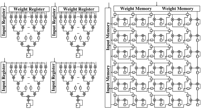
The diagram illustrates a hierarchical computational architecture composed of four identical left-side structures labeled "Input Register" and "Weight Register," and a large right-side grid labeled "Weight Memory." The left structures feature a vertical flow of interconnected components, while the right grid shows a matrix of blocks with symbolic operations.
### Components/Axes
- **Left Structures (4x)**:
- **Labels**:
- Top: "Weight Register" (repeated twice per structure)
- Bottom: "Input Register" (repeated twice per structure)
- **Components**:
- Pyramid-like hierarchy of interconnected nodes (circles with "+" and "×" symbols).
- Vertical flow from "Input Register" (bottom) to "Weight Register" (top).
- **Flow Direction**: Bottom-to-top processing.
- **Right Grid**:
- **Labels**:
- Top: "Weight Memory" (repeated twice horizontally)
- Left: "Input Memory" (vertical label)
- **Components**:
- 4x4 grid of square blocks (16 total).
- Each block contains a "+" (top-left) and "×" (bottom-right) symbol.
- Connections between blocks form a dense network.
### Detailed Analysis
- **Left Structures**:
- Each "Input Register" feeds into a tiered system of nodes, culminating in two "Weight Register" blocks at the top.
- Symbols ("+" and "×") suggest arithmetic operations (addition/subtraction) within the hierarchy.
- Repetition of structures implies parallel processing units.
- **Right Grid**:
- "Input Memory" vertically feeds into the grid, with horizontal connections between "Weight Memory" blocks.
- Each block’s "+" and "×" symbols indicate localized operations, possibly for weight updates or data aggregation.
- Grid layout suggests distributed memory storage or parallel computation.
### Key Observations
1. **Hierarchical vs. Distributed Processing**:
- Left structures emphasize vertical, layered computation.
- Right grid emphasizes horizontal, parallelized memory operations.
2. **Symbol Consistency**:
- "+" and "×" symbols are uniformly distributed, implying standardized operations across the architecture.
3. **Modularity**:
- Left structures are identical, suggesting reusable processing modules.
- Right grid’s uniformity indicates scalable memory management.
### Interpretation
This diagram likely represents a neural network or machine learning accelerator architecture. The left structures model **input processing layers** where data is transformed through arithmetic operations before being stored in **weight registers**. The right grid represents **weight memory**, where computed values are aggregated and updated in parallel. The "+" and "×" symbols highlight the role of linear algebra (e.g., matrix multiplication) in the system. The separation of input processing (left) and memory storage (right) suggests an optimized pipeline for high-throughput computation, common in hardware accelerators for AI workloads.