## Diagram: Goal Clause Tree
### Overview
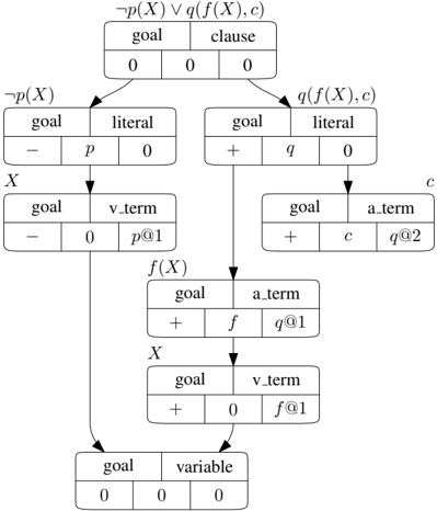
The image is a diagram representing a goal clause tree. It illustrates the decomposition of a logical expression into its constituent parts, showing the relationships between goals, literals, terms, and variables. The diagram uses boxes to represent nodes, with arrows indicating the flow of derivation. Each box contains information about the goal, type of element (clause, literal, term, variable), and associated values or symbols.
### Components/Axes
* **Nodes:** Each node is represented by a rounded rectangle. Each node is divided into two rows. The top row contains the labels "goal" and either "clause", "literal", "v_term", "a_term", or "variable". The bottom row contains data associated with the node.
* **Arrows:** Arrows indicate the flow of derivation from one node to another.
* **Root Node:** Located at the top, labeled with the expression "¬p(X) ∨ q(f(X), c)". The data row contains "0", "0", and "0".
* **Literal Nodes:** Two literal nodes branch from the root. The left node is labeled "¬p(X)" and the right node is labeled "q(f(X), c)".
* Left literal node: "goal", "literal", "-", "p", "0"
* Right literal node: "goal", "literal", "+", "q", "0"
* **v\_term and a\_term Nodes:** These nodes branch from the literal nodes.
* Left v\_term node: "X", "goal", "v\_term", "-", "0", "p@1"
* Right a\_term node: "c", "goal", "a\_term", "+", "c", "q@2"
* **a\_term and v\_term Nodes:** These nodes branch from the right literal node.
* a\_term node: "f(X)", "goal", "a\_term", "+", "f", "q@1"
* v\_term node: "X", "goal", "v\_term", "+", "0", "f@1"
* **Variable Node:** Located at the bottom, labeled "goal", "variable", "0", "0", "0".
### Detailed Analysis
* **Root Node:** The root node represents the initial goal clause: ¬p(X) ∨ q(f(X), c). The values "0", "0", "0" likely represent initial states or flags.
* **Literal Nodes:** The root node splits into two literal nodes, ¬p(X) and q(f(X), c). The "-" and "+" symbols in the "goal" column likely indicate negative and positive literals, respectively.
* **Term Nodes:** The literal nodes further decompose into term nodes (v\_term and a\_term). The values associated with these nodes (e.g., "p@1", "q@2", "f", "c") represent specific terms or function applications.
* **Variable Node:** The final node represents a variable, with the values "0", "0", "0", possibly indicating a solved or assigned state.
* **Flow:** The arrows indicate the derivation process, showing how the initial goal clause is broken down into literals, terms, and finally, variables.
### Key Observations
* The diagram illustrates a tree-like structure, representing the decomposition of a logical expression.
* The "-" and "+" symbols in the "goal" column indicate the polarity of the literals.
* The "@" symbol in the term nodes might indicate variable bindings or substitutions.
### Interpretation
The diagram represents a proof or derivation process in logic programming or automated reasoning. It shows how a complex goal clause is broken down into simpler subgoals until a solution is reached (represented by the variable node). The diagram provides a visual representation of the steps involved in proving or satisfying the initial goal clause. The specific meaning of the values and symbols (e.g., "0", "p@1", "q@2") would depend on the specific logic programming system or reasoning algorithm being used. The tree structure highlights the hierarchical nature of the derivation process, where each node represents a subgoal and its associated information.