\n
## Diagram: Resolution Refutation Proof
### Overview
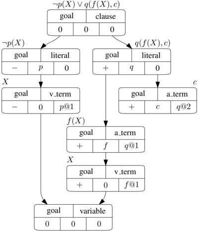
The image depicts a resolution refutation proof diagram, likely used in automated theorem proving or logic programming. It shows a tree-like structure representing the steps in a resolution process, starting from a negated goal and a clause, and branching down to derive a contradiction (empty clause). Each node in the tree represents a clause or a goal, and the arrows indicate the application of the resolution rule.
### Components/Axes
The diagram consists of rectangular nodes connected by arrows. Each node contains a table with three columns. The first column indicates a sign (+ or -), the second column contains a term or variable, and the third column contains a numerical value. The top-most node is labeled "¬p(X) ∨ q(f(X), c)". The diagram branches downwards, with labels indicating the terms and variables involved in the resolution steps.
### Detailed Analysis or Content Details
Here's a breakdown of the diagram, moving from top to bottom:
1. **Top Node:** "¬p(X) ∨ q(f(X), c)"
- Label: goal/clause
- Table: 0, 0
2. **Left Branch:** "¬p(X)"
- Label: goal
- Table: -, p, 0
3. **Right Branch:** "q(f(X), c)"
- Label: goal
- Table: +, q, 0
4. **From ¬p(X):**
- Label: X
- Table: goal, -, 0, p@1
5. **From q(f(X), c):**
- Label: c
- Table: goal, +, c, q@2
6. **From X and q(f(X), c):**
- Label: f(X)
- Table: goal, +, f, q@1
7. **From f(X):**
- Label: X
- Table: goal, +, 0, f@1
8. **Bottom Node:**
- Label: goal
- Table: variable, 0, 0
The arrows indicate the resolution steps. For example, the arrow from "¬p(X)" to "X" suggests resolving on the term 'p'. The numerical values (0, 1, 2) likely represent the resolution step number or a unique identifier for the clause. The "@" symbol followed by a number likely indicates the origin of the term in the resolution process.
### Key Observations
- The diagram demonstrates a top-down resolution refutation strategy.
- The goal is to derive a contradiction by repeatedly applying the resolution rule.
- The numerical values and "@" symbols provide a trace of the resolution process.
- The diagram shows a branching structure, indicating multiple possible resolution paths.
### Interpretation
This diagram illustrates a formal proof technique used in logic to demonstrate the unsatisfiability of a set of clauses. The process begins with the negation of the goal and attempts to derive an empty clause (a contradiction). Each step in the diagram represents the application of the resolution rule, which combines two clauses to produce a new clause. The labels and numerical values provide a detailed trace of the proof process, allowing one to verify the correctness of the derivation. The branching structure suggests that there may be multiple ways to reach a contradiction, and the diagram captures one possible path. The diagram is a visual representation of a logical argument, and its structure reflects the underlying rules of inference. The diagram does not contain any numerical data that can be extracted as values, but rather a logical flow.