TECHNICAL ASSET FINGERPRINT
7932c22e1dac4883da906186
Click to view fullscreen
Press ESC or click to close
FOUND IN PAPERS
EXPERT: healer-alpha-free VERSION 1
RUNTIME: free/openrouter/healer-alpha
INTEL_VERIFIED
\n
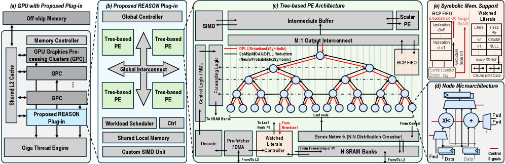
## Technical Diagram: REASON Plug-in Architecture for GPU Acceleration
### Overview
The image is a multi-part technical diagram illustrating a proposed hardware architecture called "REASON" designed to be integrated as a plug-in into a GPU. The diagram is divided into five interconnected sections labeled (a) through (e), detailing the system from the high-level GPU integration down to the microarchitecture of individual processing nodes and symbolic memory support.
### Components/Axes
The diagram is segmented into five primary regions:
1. **(a) GPU with Proposed Plug-in:** Shows the integration of the REASON plug-in within a standard GPU memory hierarchy.
2. **(b) Proposed REASON Plug-in:** Details the internal structure of the plug-in itself.
3. **(c) Tree-based PE Architecture:** A detailed view of the Processing Element (PE) array and its interconnect network.
4. **(d) Node Microarchitecture:** A close-up of the internal logic within a single processing node.
5. **(e) Symbolic Mem. Support:** Illustrates hardware structures for managing symbolic data.
**Key Labels and Components by Section:**
**(a) GPU with Proposed Plug-in (Leftmost block)**
* **Off-chip Memory** (Top)
* **Memory Controller**
* **GPU Graphics Processing Clusters (GPC)** (Two instances shown, stacked)
* **Shared L2 Cache** (Left side, connected to GPCs and Memory Controller)
* **Proposed REASON Plug-in** (Highlighted in light blue, connected to Shared L2 Cache and Giga Thread Engine)
* **Giga Thread Engine** (Bottom)
* Arrows indicate bidirectional data flow between the REASON Plug-in, Shared L2 Cache, and Giga Thread Engine.
**(b) Proposed REASON Plug-in (Second block from left)**
* **Global Controller** (Top)
* **Tree-based PE** (Four instances shown, arranged around a central interconnect)
* **Global Interconnect** (Central cross-shaped structure connecting the four PEs)
* **Workload Scheduler** (Bottom left)
* **Ctrl** (Bottom center)
* **Shared Local Memory** (Bottom)
* **Custom SIMD Unit** (Bottom right)
**(c) Tree-based PE Architecture (Central, largest block)**
* **SIMD** (Top left)
* **Intermediate Buffer** (Top center)
* **M:1 Output Interconnect** (Below Intermediate Buffer)
* **Scalar PE** (Top right)
* **BCP FIFO** (Right side, connected to Scalar PE)
* **Control Logic / MMU** (Left side)
* **Forwarding Logic** (Left side, below Control Logic)
* **Decode** (Bottom left)
* **Pre-fetcher / DMA** (Bottom left, next to Decode)
* **Watched Literals Controller** (Bottom center, with a red "From Broadcast" arrow pointing to it)
* **Benes Network (N:N Distribution Crossbar)** (Bottom center-right)
* **N SRAM Banks** (Bottom right)
* **Leaf Node** (Labels point to the bottom layer of circles in the tree)
* **From L2** (Arrow entering from bottom right)
* **To Last Node PE** (Arrow exiting bottom center)
* **From Forwarding or PE** (Arrow entering Benes Network from left)
* **Legend (within section c):**
* **Red Line:** `DPLL Broadcast (Symbolic)`
* **Blue Line:** `SpMIP/MDAG/DPLL Reduction (Neuro/Probabilistic/Symbolic)`
* The core visual is a **tree structure** of interconnected nodes (circles). Red and blue lines trace different communication paths through this tree. The tree has a root at the top, multiple intermediate layers, and leaf nodes at the bottom.
**(d) Node Microarchitecture (Bottom right inset)**
* **XIK** (A component, possibly a processing unit)
* **Adder** (Symbol: `+`)
* **Fwd** (Forwarding multiplexers, two instances)
* **Data** (Input/Output labels)
* **Control Signals** (Bottom)
* Arrows show data flow into the XIK and Adder, with forwarding paths (`Fwd`) around them.
**(e) Symbolic Mem. Support (Top right inset)**
* **BCP FIFO** (Top left)
* **Broadcast / Msg Assign** (Top center)
* **Watched Literals** (Top right, with sub-labels: `Literal`, `Head`, `x1`, `x2`, `NULL`, `Clause (Cnt) Data`)
* **Implication** (Two instances, with sub-labels: `x1=0`, `x1=1`)
* **Correl. Cache** (Bottom left)
* **Index RAM** (Bottom right)
* **Clause (Cnt) Data** (Bottom right, connected to Index RAM)
* Arrows indicate data flow between these components, including a path from "Broadcast / Msg Assign" to "Watched Literals."
### Detailed Analysis
The diagram presents a hierarchical hardware design for symbolic reasoning acceleration.
1. **System Integration (a):** The REASON Plug-in is positioned as a co-processor that interfaces directly with the GPU's Shared L2 Cache and the Giga Thread Engine, suggesting it operates at a high level within the memory hierarchy, close to the main compute units.
2. **Plug-in Structure (b):** The plug-in itself contains a Global Controller managing four Tree-based Processing Elements (PEs). These PEs communicate via a Global Interconnect. Supporting units include a Workload Scheduler, control logic (`Ctrl`), Shared Local Memory, and a Custom SIMD Unit, indicating a blend of control-driven and data-parallel processing.
3. **Tree-based PE Core (c):** This is the computational heart. A tree network of nodes facilitates parallel operations. The legend defines two critical communication protocols:
* **DPLL Broadcast (Symbolic) - Red Lines:** These paths flow *downward* from the root to the leaves, suggesting a broadcast of symbolic constraints or decisions (like in a DPLL SAT solver).
* **SpMIP/MDAG/DPLL Reduction - Blue Lines:** These paths flow *upward* from leaves to the root, indicating a reduction or aggregation of results (e.g., neuro-symbolic inference, probabilistic reasoning, or conflict analysis).
* The architecture includes dedicated hardware for instruction decode, DMA-based pre-fetching, a "Watched Literals Controller" (a key data structure in SAT solvers), a Benes Network for flexible data distribution, and multiple SRAM banks for local storage.
4. **Node-Level Detail (d):** Each node in the tree contains basic arithmetic (`Adder`) and a specialized unit (`XIK`), with forwarding paths to minimize pipeline stalls.
5. **Symbolic Memory (e):** Dedicated hardware manages symbolic concepts: FIFOs for Boolean Constraint Propagation (BCP), storage for "Watched Literals" (with fields for literal, head, and clause data), an implication queue, a correlation cache, and an index RAM. This structure is optimized for the memory access patterns of symbolic algorithms.
### Key Observations
* **Hybrid Architecture:** The design explicitly supports "Neuro/Probabilistic/Symbolic" processing (per the blue line legend), indicating a unified architecture for different AI paradigms.
* **SAT Solver Inspiration:** Multiple components (`Watched Literals`, `BCP FIFO`, `DPLL` in the legend) are direct references to algorithms used in Boolean Satisfiability (SAT) solvers, suggesting this hardware is optimized for such workloads.
* **Tree-Based Parallelism:** The core computational model is a tree, which is well-suited for divide-and-conquer algorithms common in search and reasoning tasks.
* **Custom Interconnects:** The use of a Benes Network (a non-blocking crossbar) and an M:1 Output Interconnect highlights a focus on low-latency, high-bandwidth communication between processing nodes.
* **Memory Hierarchy:** The design features a multi-level memory strategy: Off-chip Memory -> Shared L2 Cache -> Shared Local Memory (in the plug-in) -> N SRAM Banks (in the PE) -> Intermediate Buffer.
### Interpretation
This diagram details a specialized hardware accelerator designed to overcome the limitations of general-purpose GPUs for complex reasoning tasks. The **REASON Plug-in** is not just a simple compute unit; it's a self-contained subsystem with its own controller, memory, scheduler, and a massively parallel tree of processing nodes.
The architecture's primary innovation is its **hardware mapping of symbolic reasoning algorithms**. By implementing structures like watched literal queues and BCP FIFOs directly in silicon, and by creating a physical tree network that mirrors the logical tree traversal of algorithms like DPLL, the design aims to achieve orders-of-magnitude speedups over software implementations. The inclusion of neuro-symbolic and probabilistic paths indicates a forward-looking design intended for next-generation AI models that combine learning with logical reasoning.
The **spatial organization** is telling: the high-level GPU integration (a) shows *where* it fits, the plug-in view (b) shows *what* it contains, and the detailed PE (c) and node (d) views show *how* it works at the circuit level. The symbolic memory support (e) is the crucial link that feeds data into this computational tree. The entire system is a coherent pipeline from symbolic data management (e) through parallel tree-based processing (c, d) orchestrated by a global controller (b), all integrated into the GPU's memory ecosystem (a). This represents a significant architectural effort to harden AI reasoning workloads into dedicated, efficient silicon.
DECODING INTELLIGENCE...