## Diagram: Robot Wall-Following Navigation Behaviors
### Overview
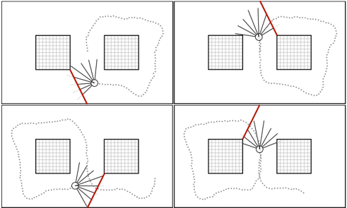
The image consists of four distinct panels arranged in a 2x2 grid. Each panel illustrates an autonomous agent (represented by a circle with a radial sensor sweep) navigating an environment containing two square obstacles. The diagrams depict different scenarios of the robot tracking the edges of these obstacles, with a specific segment of the wall highlighted in red to indicate the active tracking target. There is no text present in the image.
### Components
* **Obstacles:** Two square, grid-filled shapes representing static objects in the environment.
* **Agent:** A small circle with a fan of radial lines extending outward, representing the robot and its sensor field of view (likely LiDAR or proximity sensors).
* **Tracking Indicator:** A thick red line segment representing the specific wall edge currently being tracked or "locked onto" by the robot's sensor.
* **Trajectory:** A dotted line indicating the path taken by the agent through the environment.
### Detailed Analysis
#### Panel 1 (Top-Left)
* **Positioning:** The robot is located to the right of the left obstacle.
* **Trend/Action:** The robot is moving downwards. The sensor sweep is oriented toward the right vertical edge of the left obstacle.
* **Tracking:** The red line highlights the right vertical edge of the left obstacle, indicating the robot is following this surface.
#### Panel 2 (Top-Right)
* **Positioning:** The robot is located between the two obstacles, positioned closer to the right obstacle.
* **Trend/Action:** The robot is moving upwards and slightly to the right. The sensor sweep is oriented toward the left vertical edge of the right obstacle.
* **Tracking:** The red line highlights the left vertical edge of the right obstacle, indicating the robot is following this surface.
#### Panel 3 (Bottom-Left)
* **Positioning:** The robot is located below the gap between the two obstacles.
* **Trend/Action:** The robot is moving downwards and to the right. The sensor sweep is oriented toward the right vertical edge of the right obstacle.
* **Tracking:** The red line highlights the right vertical edge of the right obstacle, indicating the robot is following this surface.
#### Panel 4 (Bottom-Right)
* **Positioning:** The robot is located between the two obstacles, positioned closer to the left obstacle.
* **Trend/Action:** The robot is moving upwards. The sensor sweep is oriented toward the right vertical edge of the left obstacle.
* **Tracking:** The red line highlights the right vertical edge of the left obstacle, indicating the robot is following this surface.
### Key Observations
* **Consistency:** In all four panels, the robot maintains a consistent distance from the obstacle it is tracking.
* **Sensor Logic:** The radial lines represent a sensor array. The red line is always collinear with one of the sensor rays, suggesting the robot identifies the wall by detecting the closest point or the intersection of a specific sensor ray with the obstacle boundary.
* **Pathing:** The dotted lines suggest a continuous navigation loop or a specific path-planning algorithm (such as a Bug Algorithm or Wall-Following behavior) designed to navigate around obstacles.
### Interpretation
This diagram demonstrates the logic of an autonomous navigation algorithm, specifically "Wall Following." The four panels represent different states or "modes" of the robot's decision-making process as it encounters obstacles.
The robot uses its sensor array to identify the nearest obstacle edge. Once an edge is identified, the algorithm locks onto that surface (represented by the red line) and adjusts its trajectory (the dotted line) to maintain a parallel path. The transition between panels suggests the robot is capable of switching its tracking target from one obstacle to another as it moves through the environment, effectively navigating around the obstacles by "hugging" their perimeters. This is a classic representation of reactive navigation in robotics, where the agent does not need a global map but relies on local sensor data to make real-time movement decisions.