\n
## Diagram: Neural Network Framework Conversion Flow
### Overview
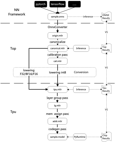
The image depicts a diagram illustrating the conversion flow of a neural network model from different frameworks (PyTorch and TensorFlow) through various stages to ultimately run on a chip. The diagram shows the process of converting a model, optimizing it for different hardware targets (Top and TPU), and performing inference at each stage. The flow is represented as a series of boxes connected by arrows, indicating the sequence of operations.
### Components/Axes
The diagram is structured into three main sections, vertically aligned: "NN Framework", "Top", and "TPU". Horizontal dashed lines separate these sections. The diagram includes the following components:
* **Frameworks:** PyTorch, TensorFlow (represented as black rectangles at the top)
* **Input File:** sample.onnx
* **Converter:** OnnxConverter
* **Intermediate Files:** origin.mlir, canonical.mlir, cali.mlir, tpu.mlir, lg.mlir, addr.mlir, sample.model
* **Passes/Operations:** canonicalize, calibration pass, lowering F32/BF16/F16, lowering int8, layer group pass, mem assign pass, codegen pass
* **Inference Stages:** Inference (repeated in Top and TPU sections)
* **Results:** ONNX Results, Top Results, Tpu Results, Chip Results
* **Runtime:** PyRuntime
* **Comparison Indicators:** "VS" (vertical dashed lines indicating comparison points)
### Detailed Analysis or Content Details
The diagram illustrates the following flow:
1. **NN Framework:** The process begins with either PyTorch or TensorFlow, both feeding into a `sample.onnx` file.
2. **OnnxConverter:** The `sample.onnx` file is then processed by the `OnnxConverter`.
3. **Top Section:**
* The `OnnxConverter` outputs `origin.mlir`.
* `origin.mlir` is processed by `canonicalize` to produce `canonical.mlir`.
* `canonical.mlir` undergoes a `calibration pass` resulting in `cali.mlir`.
* `cali.mlir` is then split into two paths: `lowering F32/BF16/F16` and `lowering int8`. These are labeled as "Conversion".
* Both lowering paths feed into `tpu.mlir`.
* `tpu.mlir` undergoes `Inference` and produces `Top Results`.
* A "VS" line indicates a comparison between `ONNX Results` and `Top Results`.
4. **TPU Section:**
* `tpu.mlir` is further processed by `layer group pass` to produce `lg.mlir`.
* `lg.mlir` is processed by `mem assign pass` to produce `addr.mlir`.
* `addr.mlir` is processed by `codegen pass` to produce `sample.model`.
* `sample.model` is processed by `PyRuntime` to produce `Chip Results`.
* `tpu.mlir` also undergoes `Inference` and produces `Tpu Results`.
* "VS" lines indicate comparisons between `Top Results` and `Tpu Results`, and between `Tpu Results` and `Chip Results`.
### Key Observations
* The diagram highlights a two-path optimization strategy: one focusing on F32/BF16/F16 lowering and the other on int8 lowering.
* The "VS" lines suggest a verification or comparison process between different stages of the conversion and inference.
* The flow is clearly segmented into Top and TPU optimization paths, indicating hardware-specific optimization.
* The use of `.mlir` file extensions suggests the use of the MLIR (Multi-Level Intermediate Representation) compiler infrastructure.
### Interpretation
This diagram illustrates a comprehensive workflow for converting and optimizing neural network models for deployment on different hardware platforms. The conversion process starts with a standard ONNX format and then leverages MLIR to optimize the model for both Top (likely a CPU or GPU) and TPU (Tensor Processing Unit) architectures. The diagram emphasizes the importance of hardware-specific optimization, as evidenced by the separate lowering paths and inference stages for each target. The "VS" lines suggest a rigorous verification process to ensure the accuracy and performance of the converted models. The use of MLIR indicates a modern approach to compiler design, allowing for flexible and efficient optimization of neural network models. The diagram suggests a focus on quantization (int8 lowering) as a key optimization technique for TPUs. The overall flow demonstrates a sophisticated pipeline for deploying neural networks across diverse hardware environments.