TECHNICAL ASSET FINGERPRINT
7b940919b8b56f451d6bd6f1
Click to view fullscreen
Press ESC or click to close
FOUND IN PAPERS
EXPERT: healer-alpha-free VERSION 1
RUNTIME: free/openrouter/healer-alpha
INTEL_VERIFIED
## [Diagram]: Neural Network Model Conversion Pipeline
### Overview
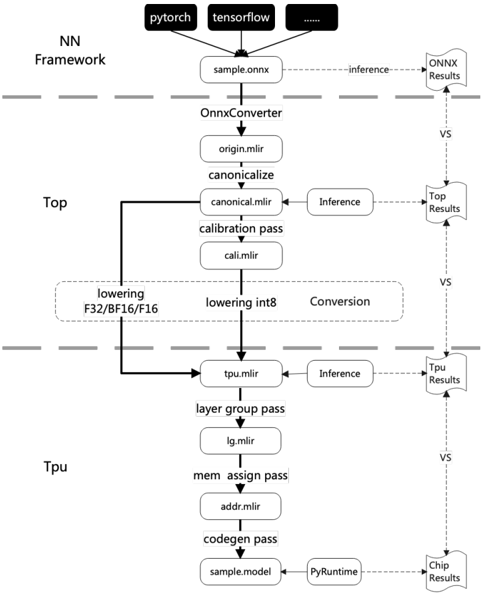
This image is a technical flowchart illustrating a multi-stage pipeline for converting neural network models from high-level frameworks (like PyTorch and TensorFlow) into an optimized format for execution on a TPU (Tensor Processing Unit). The diagram is segmented into three horizontal layers by dashed lines, representing distinct processing environments or stages: **NN Framework**, **Top**, and **Tpu**. A parallel verification flow on the right side compares results at each major stage.
### Components/Axes
The diagram is structured vertically, with the primary data flow moving from top to bottom. Key components are organized as follows:
**1. NN Framework (Top Layer)**
* **Input Sources:** Three boxes at the very top represent source frameworks:
* `pytorch`
* `tensorflow`
* A black box with `...` (indicating other frameworks).
* **Initial Model:** All sources point to a single box labeled `sample.onnx`, representing a model exported in the ONNX (Open Neural Network Exchange) format.
* **Verification Path:** A dashed arrow labeled `inference` leads from `sample.onnx` to a document icon labeled `ONNX Results`.
**2. Top (Middle Layer)**
* **Conversion Start:** The `sample.onnx` file is processed by the `OnnxConverter`, producing `origin.mlir`.
* **Canonicalization:** `origin.mlir` undergoes a `canonicalize` step, resulting in `canonical.mlir`.
* **Verification Path:** A dashed arrow labeled `Inference` leads from `canonical.mlir` to a document icon labeled `Top Results`.
* **Calibration:** `canonical.mlir` passes through a `calibration pass` to produce `cal.mlir`.
* **Lowering/Conversion:** A large dashed box labeled `Conversion` encompasses two parallel processes:
* `lowering F32/BF16/F16` (for floating-point types).
* `lowering int8` (for integer quantization).
* **Output to TPU:** The output of the conversion stage is `tpu.mlir`.
**3. Tpu (Bottom Layer)**
* **Input:** `tpu.mlir` is the entry point for this layer.
* **Verification Path:** A dashed arrow labeled `Inference` leads from `tpu.mlir` to a document icon labeled `Tpu Results`.
* **Layer Grouping:** `tpu.mlir` undergoes a `layer group pass`, producing `lg.mlir`.
* **Memory Assignment:** `lg.mlir` is processed by a `mem assign pass`, resulting in `addr.mlir`.
* **Code Generation:** `addr.mlir` goes through a `codegen pass`, producing the final executable model: `sample.model`.
* **Final Execution & Verification:** `sample.model` is executed via `PyRuntime`. A dashed arrow leads to the final document icon labeled `Chip Results`.
**4. Verification Flow (Right Side)**
* A vertical series of document icons (`ONNX Results`, `Top Results`, `Tpu Results`, `Chip Results`) are connected by downward-pointing dashed arrows labeled `VS`.
* This indicates a comparative validation process where the outputs (results) from each major stage of the pipeline are checked against each other to ensure correctness and consistency throughout the conversion.
### Detailed Analysis
The diagram details a precise, multi-step compilation and optimization workflow:
1. **Framework Agnostic Start:** The process begins by accepting models from various popular deep learning frameworks, unified via the ONNX standard (`sample.onnx`).
2. **Intermediate Representation (IR) Evolution:** The model is progressively transformed through several Intermediate Representation (IR) formats, all based on MLIR (Multi-Level IR):
* `origin.mlir` -> `canonical.mlir` -> `cal.mlir` -> `tpu.mlir` -> `lg.mlir` -> `addr.mlir`.
3. **Key Transformation Passes:**
* **Canonicalization:** A standard optimization pass to simplify the IR.
* **Calibration:** Likely analyzes the model to determine parameters for quantization.
* **Lowering/Conversion:** A critical step where the model's data types are converted (lowered) from high-precision floats (F32, BF16, F16) to lower-precision integers (int8) for efficient hardware execution.
* **Layer Group Pass:** Optimizes the model structure for the target hardware's architecture.
* **Memory Assignment Pass:** Allocates physical memory addresses for model data and operations.
* **Code Generation Pass:** Translates the final IR into machine-executable code (`sample.model`).
4. **Continuous Verification:** The `VS` (versus) flow on the right is a crucial component. It shows that inference is run at multiple stages (`ONNX`, `Top`, `Tpu`, `Chip`), and the results are compared. This ensures that each transformation step preserves the model's functional correctness.
### Key Observations
* **Structured Pipeline:** The workflow is highly linear and modular, with clear separation of concerns between framework-level, compiler-level (`Top`), and hardware-specific (`Tpu`) optimizations.
* **Quantization Focus:** The explicit `lowering int8` path highlights that model quantization (reducing numerical precision) is a central goal of this pipeline, aimed at improving inference speed and efficiency on the TPU.
* **MLIR-Centric:** The use of `.mlir` file extensions throughout indicates the entire toolchain is built upon the MLIR compiler infrastructure, which is designed for building domain-specific compilers.
* **End-to-End Validation:** The presence of the `VS` comparison flow suggests a robust development or deployment process where numerical accuracy is validated at every major transformation boundary.
### Interpretation
This diagram represents a **model compilation and deployment pipeline** for specialized AI hardware (a TPU). Its purpose is to take a generic neural network model and transform it into a highly optimized, hardware-specific executable.
* **What it demonstrates:** It shows the journey from a portable, software-friendly model format (ONNX) to a low-level, hardware-optimized binary (`sample.model`). The process involves not just format conversion but also significant optimization (canonicalization, quantization, layer grouping, memory planning).
* **Relationships:** The `NN Framework` layer is the user-facing entry point. The `Top` layer acts as a hardware-agnostic compiler, performing major optimizations and lowering. The `Tpu` layer is the hardware-specific backend, handling final code generation and memory layout for the target chip. The verification flow is a cross-cutting concern that ensures integrity across all layers.
* **Underlying Purpose:** The pipeline is designed to bridge the gap between high-level AI research frameworks and the need for maximum performance and efficiency on custom silicon. The emphasis on `int8` lowering and the multi-stage verification strongly suggests this is a production-oriented toolchain where both performance (speed, power) and numerical fidelity are critical requirements. The use of MLIR points to a modern, extensible compiler architecture.
DECODING INTELLIGENCE...